
Datasheet

Chapter 2: Installation
2-9
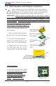
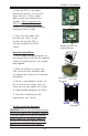
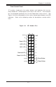
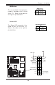
Power LED
The Power LED connection is lo-
cated on pins 15 and 16 of JF1.
Refer to the table on the right for
pin definitions.
NMI Button
The non-maskable interrupt button
header is located on pins 19 and
20 of JF1. Refer to the table on
the right for pin definitions.
Pin
Number
19
20
Definition
Control
Ground
NMI Button Pin
Definitions (JF1)
Pin
Number
15
16
Definition
Vcc
Control
PWR_LED Pin Definitions
(JF1)
.
%
0
R
X
VH
',00 $
',00 %
',00 $
',00 %
',00 $
',00 %
7
X
P
Z
D
WH
U
1
R
UWK
%
ULG
J
H
0
D
UY
H
OO
,'(
,'(
8
6
%
&20
&20
SLQ
3:
$7;3:5
-3)
)RUFH
3:2Q
0LF
-
$XGLR
(QDEOH
6
,2
3
&
,
(
[
3&,; 0+]
3&,; 0+]
%
D
WWH
U\
:
2
5
-3
6
)$1
/$1
$
X
[
LQ
&
'
LQ
3&, 0+]
-
-
-3
/
3&,( ;
)ORSS\
3
:
/
(
'
.
/
6$7$
&
K
DVVLV
,Q
WUX
VLR
Q
+DQFH
5DSLGV
86%
-)
-%7
-:
'
-
'Q/LQHB,Q
8S/LQHB2XW
-
-
-
6
/
(
'
6
$
7
$
/
(
'
6
$
7
$
,
&
;
'
$
/
7
*
:
DWFK
'
RJ
/
$
1
(
Q
D
E
OH
)
D
Q
)
D
Q
-:
2
/
-)
6
S
N
U
&
/
&
0
2
6
)DQ
)3 &WOU
)
D
Q
)
D
Q
&
38
&
38
60% GDWDWR3&,(Q
60%&/.WR3&, (Q
&1
$
O0
5
VH
W
-
-
3:
)DXOW
60% 3:
-
-
-
3&, 0+]
-
3:
3:
-
/$1
&75/
%,26
3
ULQ
WH
U
6SNU
6$7$
6$7$
6$7$
-/
6$7$
&75/
0DUYHOO 6$7$
(QDEOH
+6$7$
+6$7$
-6
-6
'6
'6
'
6
'
6
'
6
'6
'6
'
6
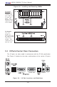
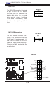
Power Butto
n
Overheat LED
1
NIC1 LED
Reset Button
2
P
ower Fail LED
HDD LED
Power LED
Reset
Pwr
Vcc
Vcc
Vcc
Vcc
Ground
Ground
1920
Vcc
X
Ground
NMI
X
x
x
NMI
PWR LED