
Datasheet

2-10
X6DAL-G/X6DAL-TG User's Manual
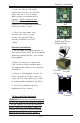
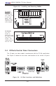
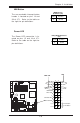
NIC1 LED Indicators
The NIC (Network Interface Con-
troller) LED connections for the
GLAN port1 is located on pins 11
and 12 of JF1. Attach the NIC LED
cable to display network activity.
Refer to the tables on the right for
pin definitions.
NIC1 LED Pin
Definitions
(JF1)
Pin
Number
11
12
Definition
Vcc
GND
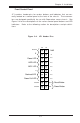
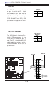
HDD LED
The HDD LED connection is located
on pins 13 and 14 of JF1. Attach
the hard drive LED cable here to
display disk activity (for any hard
drives on the system, including
SCSI, Serial ATA and IDE). See
the table on the right for pin defini-
tions.
HDD LED Pin
Definitions
(JF1)
Pin
Number
13
14
Definition
Vcc
HD Active
.
%
0
R
X
VH
',00 $
',00 %
',00 $
',00 %
',00 $
',00 %
7
X
P
Z
D
WH
U
1
R
UWK
%
ULG
J
H
0
D
UY
H
OO
,'(
,'(
8
6
%
&20
&20
SLQ
3:
$7 ; 3 : 5
-3)
)RUFH
3:2Q
0LF
-
$XGLR
(QDEOH
6
,2
3
&
,
(
[
3&,; 0+]
3&,; 0+]
%
D
WWH
U\
:
2
5
-3
6
)$1
/$1
$
X
[
LQ
&
'
LQ
3&, 0+]
-
-
-3
/
3&,( ;
)ORSS\
3
:
/
(
'
.
/
6$7$
&
KDVVLV
,Q
WUX
VLR
Q
+DQFH
5DSLGV
86%
-)
-%7
-:
'
-
'Q/LQHB,Q
8S/LQHB2XW
-
-
-
6
/
(
'
6
$
7
$
/
(
'
6
$
7
$
,
&
;
'
$
/
7
*
:
DWFK
'
RJ
/
$
1
(
Q
D
E
OH
)
D
Q
)
D
Q
-:
2
/
-)
6
S
N
U
&
/
&
0
2
6
)DQ
)3 &WOU
)
D
Q
)
D
Q
&
38
&
38
60% GDWDWR3&,(Q
60%&/.WR3&, (Q
&1
$
O0
5
VH
W
-
-
3:
)DXOW
60% 3:
-
-
-
3&, 0+]
-
3:
3:
-
/$1
&75/
%,26
3
ULQ
WH
U
6SNU
6$7$
6$7$
6$7$
-/
6$7$
&75/
0DUYHOO 6$7$
(QDEOH
+6$7$
+6$7$
-6
-6
'6
'6
'
6
'
6
'
6
'6
'6
'
6
Power Butto
n
Overheat LED
1
NIC1 LED
Reset Button
2
P
ower Fail LED
HDD LED
Power LED
Reset
Pwr
Vcc
Vcc
Vcc
Vcc
Ground
Ground
1920
Vcc
X
Ground
NMI
X
x
x
NIC1 LED
HDD LED