
Datasheet


Chapter 2: Installation
2-11
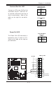
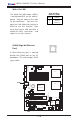
Overheat/Fan Fail LED
Connect an LED to the OH/Fan Fail
connection on pins 7 and 8 of JF1
to provide advanced warning of
chassis overheating. Refer to the
table on the right for pin defini-
tions.
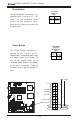
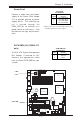
Power Fail LED
The Power Fail LED connection is
located on pins 5 and 6 of JF1.
Refer to the table on the right for
pin definitions.
Overheat/Fan Fail
LED Pin Definitions
(JF1)
Pin
Number
7
8
Definition
Vcc
GND
Power Fail LED Pin
Definitions
(JF1)
Pin
Number
5
6
Definition
Vcc
GND
.
%
0
R
X
VH
',00 $
',00 %
',00 $
',00 %
',00 $
',00 %
7
X
P
Z
D
WH
U
1
R
UWK
%
ULG
J
H
0
D
UY
H
OO
,'(
,'(
8
6
%
&20
&20
SLQ
3:
$7;3:5
-3)
)RUFH
3:2Q
0LF
-
$XGLR
(QDEOH
6
,2
3
&
,
(
[
3&,; 0+]
3&,; 0+]
%
D
WWH
U\
:
2
5
-3
6
)$1
/$1
$
X
[
LQ
&
'
LQ
3&, 0+]
-
-
-3
/
3&,( ;
)ORSS\
3
:
/
(
'
.
/
6$7$
&
K
DVVLV
,Q
WUX
VLR
Q
+DQFH
5DSLGV
86%
-)
-%7
-:
'
-
'Q/LQHB,Q
8S/LQHB2XW
-
-
-
6
/
(
'
6
$
7
$
/
(
'
6
$
7
$
,
&
;
'
$
/
7
*
:
DWFK
'
RJ
/
$
1
(
Q
D
E
OH
)
D
Q
)
D
Q
-:
2
/
-)
6
S
N
U
&
/
&
0
2
6
)DQ
)3 &WOU
)
D
Q
)
D
Q
&
38
&
38
60% GDWDWR3&,(Q
60%&/.WR3&, (Q
&1
$
O0
5
VH
W
-
-
3:
)DXOW
60% 3:
-
-
-
3&, 0+]
-
3:
3:
-
/$1
&75/
%,26
3
ULQ
WH
U
6SNU
6$7$
6$7$
6$7$
-/
6$7$
&75/
0DUYHOO 6$7$
(QDEOH
+6$7$
+6$7$
-6
-6
'6
'6
'
6
'
6
'
6
'6
'6
'
6
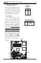
Power Butto
n
Overheat LED
1
NIC1 LED
Reset Button
2
P
ower Fail LED
HDD LED
Power LED
Reset
Pwr
Vcc
Vcc
Vcc
Vcc
Ground
Ground
1920
Vcc
X
Ground
NMI
X
x
x
OH LED
PWR Fail LED
Overheat/Fan Fail
LED
State
Solid
Blink
Message
Overheat
Fan Fail