
Datasheet


Chapter 2: Installation
2-17
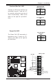
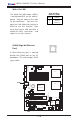
Power Fault
Connect a cable from your power
supply to the Power Fault header
(J7) to provide warning of power
supply failure. This warning sig-
nal is passed through the
PWR_LED pin to indicate of a
power failure on the chassis. See
the table on the right for pin defini-
tions.
Power Fault
Pin Definitions
Pin
Number
1
2
3
4
Definition
P/S 1 Fail Signal
P/S 2 Fail Signal
P/S 3 Fail Signal
Reset (from MB)
Note: This feature is only available when using
redundant Supermicro power supplies.
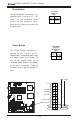
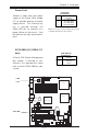
SATA SMB (I
2
C)(*X6DAL-TG
only)
A Serial ATA System Management
Bus header is located at J35.
Connect the appropriate cable
here to utilize SATA SMB on your
system.
SATA SMB (J35)
Pin Definitions
Pin
Number
1
2
3
Definition
Data
Ground
Clock
.
%
0
R
X
VH
',00 $
',00 %
',00 $
',00 %
',00 $
',00 %
7
XP
Z
DWHU
1
RUWK %
ULGJH
0
DUYHOO
,'(
,'(
86%
&
2
0
&
2
0
SLQ
3:
$7 ; 3 : 5
-3)
)RUFH
3:2Q
0LF
-
$XGLR
(QDEOH
6
,2
3&,( [
3&,; 0+]
3&,; 0+]
%
DWWHU\
:
2
5
-3
6
)$1
/
$
1
$X[ LQ
&'LQ
3&, 0+]
-
-
-3/
3&,( ;
)ORSS\
3: /('./
6$7$
&
K
DVVLV
,Q
WUXVLRQ
+DQFH
5DSLGV
86%
-)
-%7
-:
'
-
'Q/LQHB,Q
8S/LQHB2XW
-
-
-6
/
(
'
6
$
7
$
/
(
'
6
$
7
$
,
&
;
'
$
/
7
*
:
DWFK
'
RJ
/
$
1
(
QDEOH
)DQ
)DQ
-:2/
-)
6SNU
&/ &026
)DQ
)3 &WOU
)DQ
)DQ
&38
&38
6
0
%
G
DWD WR
3
&
,(
Q
6
0
%
&
/
.
WR
3
&
, (
Q
&1
$
O0
5
VHW
-
-
3:
)DXOW
60
%
3:
-
-
-
3&, 0+]
-
3:
3:
-
/
$
1
&
7
5
/
%
,2
6
3ULQWHU
6SNU
6$7$
6$7$
6$7$
-/
6
$
7
$
&
7
5
/
0DUYHOO 6$7$
(QDEOH
+6$7$
+6$7$
-6
-6
'6
'6
'6
'6
'6
'6
'6
'6
PWR
Fault
SATA SMB