
Datasheet


2-18
X6DAL-G/X6DAL-TG User's Manual
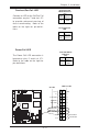
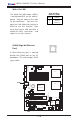
SMB Power (I
2
C)
Connector
I
2
C Connector, located at J27,
monitors the status of PWR Sup-
ply, Fan and system temperature.
SMB PWR
Pin Definitions (J27)
Pin #
1
2
3
4
5
Definition
Clock
SMB Data
N/A
N/A
N/A
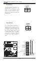
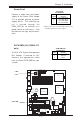
CD-In Header
There is a 4-pin CD header on the
motherboard. This allows you to
use the onboard sound for audio
CD playback. Connect the audio
cable from your CD drive to the
header. See the tables at right for
pin definitions.
Audio CD Header Pin Definitions
(CD2)
Pin
Number
1
2
3
4
Definition
Right Stereo Signal
Ground
Ground
Left Stereo Signal
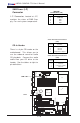
Audio CD Header Pin Definitions
(CD1)
Pin
Number
1
2
3
4
Definition
Left Stereo Signal
Ground
Ground
Right Stereo Signal
.
%
0
RXVH
',00 $
',00 %
',00 $
',00 %
',00 $
',00 %
7
XP
Z
DWHU
1
RUWK %
ULGJH
0
DUYHOO
,'(
,'(
86%
&20
&20
SLQ
3:
$7; 3:5
-3)
)RUFH
3:2Q
0
LF
-
$
X
GLR
(
QDE
OH
6,2
3&,( [
3
&
,;
0
+
]
3
&
,;
0
+
]
%
DWWHU\
:
2
5
-3
6
)$1
/$1
$
X
[
LQ
&
'
LQ
3
&
,
0
+
]
-
-
-3
/
3
&
,(
;
)
OR
S
S
\
3: /('./
6$7$
&
K
DVVLV
,QWUX
VLR
Q
+DQFH
5DSLGV
86%
-)
-%7
-:
'
-
'
Q/
LQ
HB
,Q
8
S
/
LQ
HB2
X
W
-
-
-6/('
6$7$
/('
6
$
7
$
,
&
;
'
$
/
7
*
:
DWFK
'
R
J
/
$
1
(
QDEOH
)
DQ
)
DQ
-:
2
/
-)
6
S
N
U
&
/
&
0
2
6
)
DQ
)3 &WOU
)
DQ
)
DQ
&
38
&
38
60% GDWD WR3&,(Q
60%&/.WR3&, (Q
&1
$O05VHW
-
-
3:
)DXOW
60
% 3:
-
-
-
3
&
,
0
+
]
-
3:
3:
-
/$1
&75/
%,26
3
ULQ
WHU
6SNU
6$7$
6$7$
6$7$
-/
6$7$
&75/
0DUYHOO 6$7$
(QDEOH
+6$7$
+6$7$
-6
-6
'6
'6
'
6
'
6
'
6
'6
'6
'
6
CD In
SMB PWR