
Datasheet


2-20
X6DAL-G/X6DAL-TG User's Manual
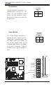
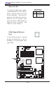
2-6 Jumper Settings
Explanation of
Jumpers
To modify the operation of the
motherboard, jumpers can be
used to choose between
optional settings. Jumpers
create shorts between two pins
to change the function of the
connector. Pin 1 is identified
with a square solder pad on
the printed circuit board. See
the motherboard layout pages
for jumper locations.
Note: On two pin jumpers,
"Closed" means the jumper is
on and "Open" means the
jumper is off the pins.
Connector
Pins
Jumper
Cap
Setting
Pin 1-2 short
3 2 1
3 2 1
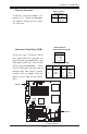
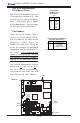
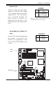
LAN Enable/Disable
JPL1 enables or disable the Giga-
bit LAN port on the motherboard.
See the table on the right for
jumper settings. The default set-
ting is enabled.
Jumper
Position
Pins 1-2
Pins 2-3
Definition
Enabled
Disabled
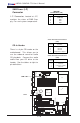
GLAN
Enable/Disable
Jumper Settings
(JPL1)
.%
0RXVH
',00 $
',00 %
',00 $
',00 %
',00 $
',00 %
7XPZDWHU
1RUWK %ULGJH
0DUYHOO
,'(
,'(
8
6%
&
2
0
&
2
0
SLQ
3:
$7; 3:5
-3)
)RUFH
3:2Q
0LF
-
$XGLR
(QDEOH
6
,2
3&,( [
3&,; 0+]
3&,; 0+]
%DWWHU\
:
25
-3
6
)$1
/
$
1
$
X
[
LQ
&
'
LQ
3&, 0+]
-
-
-3
/
3&,( ;
)ORSS\
3: /('./
6$7$
&
K
DVVLV
,QWUX
VLR
Q
+DQFH
5DSLGV
86%
-)
-%7
-:
'
-
'Q/LQHB,Q
8S/LQHB2XW
-
-
-6
/
(
'
6
$
7
$
/
(
'
6
$
7
$
,
&
;
'
$
/
7
*
:
DWFK
'
R
J
/$1 (QDEOH
)
D
Q
)
D
Q
-:
2
/
-)
6
S
N
U
&
/
&
0
2
6
)DQ
)3 &WOU
)
D
Q
)
D
Q
&
3
8
&
3
8
6
0
%
G
D
WD
WR
3
&
,(
Q
6
0
%
&
/
.
WR
3
&
, (
Q
&1
$O05VHW
-
-
3:
)DXOW
6
0
%
3
:
-
-
-
3&, 0+]
-
3:
3:
-
/
$
1
&
7
5
/
%
,2
6
3
ULQ
WH
U
6SNU
6$7$
6$7$
6$7$
-/
6$7$
&75/
0DUYHOO 6$7$
(QDEOH
+6$7$
+6$7$
-6
-6
'6
'6
'
6
'
6
'
6
'6
'6
'
6
LAN Enable