
Datasheet

Chapter 2: Installation
2-7
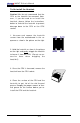
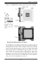
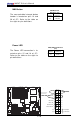
To Remove:
Use your thumbs to gently push near the edge of both ends
of the module. This should release it from the slot.
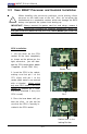
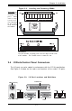
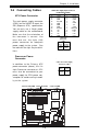
2-4 I/OPorts/Control Panel Connectors
The I/O ports are color coded in conformance with the PC 99 specification.
See Figure 2-3 below for the colors and locations of the various I/O ports.
Figure 2-3. I/O Port Locations and Definitions
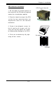
Figure 2-2. Installing and Removing DIMMs
To Install: In-
sert module
vertically and
press down
until it snaps
intoplace.
Pay attention
to the align-
ment notch at
the bottom.
Mouse (Green)
Keyboard (Purple)
USB 0/1
COM1
Video
Parallel Port
LAN1 LAN2