
Datasheet
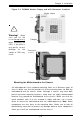
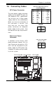

Chapter 2: Installation
2-9
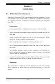
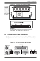
LAN1
®
JLAN1
S
UPER X6DHT-G
LAN2
DIMM 2A
DIMM 2B
DIMM 3A
DIMM 3B
DIMM 4A
DIMM 4B
DIMM 1B
DIMM 1A
12V 8-pin
PWR
SMBus
PWR
JF1
FP Control
OH
LED
IPMI
IDE2
Floppy
COM2
BIOS
Fan4
SATA0
SMB
PCI-X100 MHz
PCI-X 100 MHz/ZCR
PCI-X 3 133 MHz
Battery
JPL1
RAGE-
XL
PCI-E X8
Lindenhurst
North
Bridge
VGA
COM1
USB
0/1
KB/
Mouse
Fan6
Fan5
ATX PWR
12V 4-Pin
PWR
Parrallel
Port
24-Pin
Fan7
JPW1
Fan8
CPU1
JWOR
S I/O
PSF
Fan3
IDE1
PCI-33 MHz
USB2/3
ICH
JD1
JPG1
JWD
Slot1
Slot2
Slot3
Slot4
Slot5
Slot6
PCI-E X8
GLAN
CTLR
6300ESB
Buzzer
PXH
JBT1
SATA1
SATA0
SATA1
SATA2
SATA3
SATA4
SATA5
SATA6
SATA7
Marvell
Intel
GLAN
CTLR
JPL2
M-SATA
Act LED
JL1
M-SATA
I
2
C
JPS1
SATA
Controller
Fan2
Fan1
JAR
J3P
CPU2
E7520
Bank1
Bank2
Bank3
Bank4
WOL
DS9
DS1
DS10
DS2
DS11
DS3
DS12
DS4
DS13
DS5
DS14
DS6
DS15
DS7
DS16
DS8
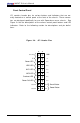
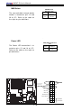
ATX Power Supply 24-pin Connector
Pin Definitions(JPW1)
Pin Number Definition
13 +3.3V
14 -12V
15 COM
16 PS_ON#
17 COM
18 COM
19 COM
20 Res(NC)
21 +5V
22 +5V
23 +5V
24 COM
Pin Number Definition
1 +3.3V
2 +3.3V
3 COM
4 +5V
5 COM
6 +5V
7 COM
8 PWR_OK
9 5VSB
10 +12V
11 +12V
12 +3.3V
2-5 Connecting Cables
Pins
1 thru 4
5 thru 8
Definition
Ground
+12v
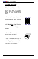
8-Pin +12v Power Supp
ly
Connector (J1D1)
Processor Power
Connector
In addition to the Primary ATX
power connector (above), the 12v
8-pin Processor connector at J1D1
must also be connected to your
power supply for CPU power con-
sumption to avoid causing instabil-
ity to the system.
Pins #
1 & 2
3 & 4
Definition
Ground
+12 V
+12V 4-pin
Connector
(J38)
24-Pin ATX PWR 8-Pin 12V PWR
4-Pin12V CPU PWR
ATX Power Connector
The main power supply connector
(JPW1) on the X6DHT-G meets the
SSI (Superset ATX) specification.
You can only use a 24-pin power
supply cable on the motherboard.
Make sure that the orientation of
the connector is correct. You
must also use the 4-pin (J38)
power connector for adequate
power supply to the system. See
the table on the right for pin defini-
tions.