
Datasheet


2-20
X6DHT-G User's Manual
Marvell SATA SMB Power
(I
2
C) Connector
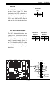
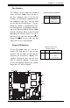
The Marvell SATA I
2
C Connector
(JS10), located between IDE1 Slot
and Chassis Intrusion Header,
monitors the status of PWR Sup-
ply, Fan and system temperature
for Marvell Serial ATA ports. See
the table on the right for pin defini-
tions.
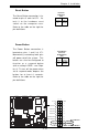
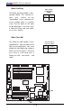
M-SATA_ACT_Output Pin Definitions
(JS9)
Pin # Definition
1 SATA0_Act
2 SATA1_Act
3 SATA2_Act
4 SATA3_Act
5 LED_COM
Pin# Definition
6 SATA4_Ac
t
7 SATA5_Ac
t
8 SATA6_Ac
t
9 SATA7_Ac
t
10 NC
Marvell SATA Activity
Output LED Header
Marvell Serial ATA Activity Output
LED Header(JS9), located be-
tween Fan4 Header and Chassis
Intrusion Header, displays the sta-
tus of Marvell's SATA Activities.
See the table on the right for pin
definitions.
LAN1
®
JLAN1
S
UPER X6DHT-G
LAN2
DIMM 2A
DIMM 2B
DIMM 3A
DIMM 3B
DIMM 4A
DIMM 4B
DIMM 1B
DIMM 1A
12V 8-pin
PWR
SMBus
PWR
JF1
FP Control
OH
LED
IPMI
IDE2
Floppy
COM2
BIOS
Fan4
SATA0
SMB
PCI-X100 MHz
PCI-X 100 MHz/ZCR
PCI-X 3 133 MHz
Battery
JPL1
RAGE-
XL
PCI-E X8
Lindenhurst
North
Bridge
VGA
COM1
USB
0/1
KB/
Mouse
Fan6
Fan5
ATX PWR
12V 4-Pin
PWR
Parrallel
Port
24-Pin
Fan7
JPW1
Fan8
CPU1
JWOR
S I/O
PSF
Fan3
IDE1
PCI-33 MHz
USB2/3
ICH
JD1
JPG1
JWD
Slot1
Slot2
Slot3
Slot4
Slot5
Slot6
PCI-E X8
GLAN
CTLR
6300ESB
Buzzer
PXH
JBT1
SATA1
SATA0
SATA1
SATA2
SATA3
SATA4
SATA5
SATA6
SATA7
Marvell
Intel
GLAN
CTLR
JPL2
M-SATA
Act LED
JL1
M-SATA
I
2
C
JPS1
SATA
Controller
Fan2
Fan1
JAR
J3P
CPU2
E7520
Bank1
Bank2
Bank3
Bank4
WOL
DS9
DS1
DS10
DS2
DS11
DS3
DS12
DS4
DS13
DS5
DS14
DS6
DS15
DS7
DS16
DS8
M-SATA I
2
C
M-SATA ACT
OUTPUT
Pin
Number
1
2
3
Definition
TWSI_SDA
Ground
TWSI_SCK
Marvell SATA I
2
C Pin
Definitions (JS10)