
Datasheet


Chapter 2: Installation
2-23
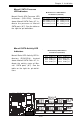
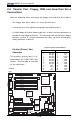
LAN1
®
JLAN1
S
UPER X6DHT-G
LAN2
DIMM 2A
DIMM 2B
DIMM 3A
DIMM 3B
DIMM 4A
DIMM 4B
DIMM 1B
DIMM 1A
12V 8-pin
PWR
SMBus
PWR
JF1
FP Control
OH
LED
IPMI
IDE2
Floppy
COM2
BIOS
Fan4
SATA0
SMB
PCI-X100 MHz
PCI-X 100 MHz/ZCR
PCI-X 3 133 MHz
Battery
JPL1
RAGE-
XL
PCI-E X8
Lindenhurst
North
Bridge
VGA
COM1
USB
0/1
KB/
Mouse
Fan6
Fan5
ATX PWR
12V 4-Pin
PWR
Parrallel
Port
24-Pin
Fan7
JPW1
Fan8
CPU1
JWOR
S I/O
PSF
Fan3
IDE1
PCI-33 MHz
USB2/3
ICH
JD1
JPG1
JWD
Slot1
Slot2
Slot3
Slot4
Slot5
Slot6
PCI-E X8
GLAN
CTLR
6300ESB
Buzzer
PXH
JBT1
SATA1
SATA0
SATA1
SATA2
SATA3
SATA4
SATA5
SATA6
SATA7
Marvell
Intel
GLAN
CTLR
JPL2
M-SATA
Act LED
JL1
M-SATA
I
2
C
JPS1
SATA
Controller
Fan2
Fan1
JAR
J3P
CPU2
E7520
Bank1
Bank2
Bank3
Bank4
WOL
DS9
DS1
DS10
DS2
DS11
DS3
DS12
DS4
DS13
DS5
DS14
DS6
DS15
DS7
DS16
DS8
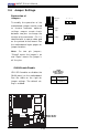
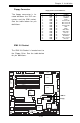
Watch Dog Enable
JWD controls Watch Dog, a system monitor
that takes action when a software application
freezes the system. Pins 1-2 will have WD
reset the system if a program freezes. Pins
2-3 will generate a non-maskable interrupt for
the program that has frozen (requires soft-
ware implementation). Watch Dog must also
be enabled in BIOS.
Jumper
Position
Pins 1-2
Pins 2-3
Open
Definition
WD to Reset
WD to NMI
Disabled
Watch Dog
Jumper Settings (JWD)
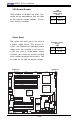
CMOS Clear
JBT1 is used to clear CMOS. Instead of pins, this "jumper" consists of
contact pads to prevent the accidental clearing of CMOS. To clear CMOS,
use a metal object such as a small screwdriver to touch both pads at the
same time to short the connection. Always remove the AC power cord
from the system before clearing CMOS.
Note: For an ATX power supply, you must completely shut down the
system, remove the AC power cord and then short JBT1 to clear CMOS.
Do not use the PW_ON connector to clear CMOS.
Clear CMOS
Watch Dog Enable