
Datasheet
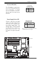

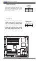


Chapter 2: Installation
2-25
LAN1
®
JLAN1
S
UPER X6DHT-G
LAN2
DIMM 2A
DIMM 2B
DIMM 3A
DIMM 3B
DIMM 4A
DIMM 4B
DIMM 1B
DIMM 1A
12V 8-pin
PWR
SMBus
PWR
JF1
FP Control
OH
LED
IPMI
IDE2
Floppy
COM2
BIOS
Fan4
SATA0
SMB
PCI-X100 MHz
PCI-X 100 MHz/ZCR
PCI-X 3 133 MHz
Battery
JPL1
RAGE-
XL
PCI-E X8
Lindenhurst
North
Bridge
VGA
COM1
USB
0/1
KB/
Mouse
Fan6
Fan5
ATX PWR
12V 4-Pin
PWR
Parrallel
Port
24-Pin
Fan7
JPW1
Fan8
CPU1
JWOR
S I/O
PSF
Fan3
IDE1
PCI-33 MHz
USB2/3
ICH
JD1
JPG1
JWD
Slot1
Slot2
Slot3
Slot4
Slot5
Slot6
PCI-E X8
GLAN
CTLR
6300ESB
Buzzer
PXH
JBT1
SATA1
SATA0
SATA1
SATA2
SATA3
SATA4
SATA5
SATA6
SATA7
Marvell
Intel
GLAN
CTLR
JPL2
M-SATA
Act LED
JL1
M-SATA
I
2
C
JPS1
SATA
Controller
Fan2
Fan1
JAR
J3P
CPU2
E7520
Bank1
Bank2
Bank3
Bank4
WOL
DS9
DS1
DS10
DS2
DS11
DS3
DS12
DS4
DS13
DS5
DS14
DS6
DS15
DS7
DS16
DS8
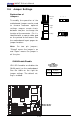
3rd PWR Supply PWR Fault Detect
(J3P)
The system can notify you in the event of a
power supply failure. This feature as-
sumes that three power supply units are
installed in the chassis, with one acting as
a backup. If you only have one or two
power supply units installed, you should
disable this (the default setting) with J3P to
prevent false alarms.
Jumper
Position
Open
Closed
Definition
Disabled
Enabled
3rd PWR Supply PWR
Fault Detect
Jumper Settings (J3P)
3rd PWR Fault
Detect
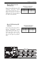
SATA Controller Enable
JPS1 enables or disables the AIC 8140
Marvell SATA Controller on the mother-
board. See the table on the right for jumper
settings. The default setting is enabled.
Jumper
Position
Pins 1-2
Pins 2-3
Definition
Enabled
Disabled
SATA Controller
Enable/Disable
Jumper Settings
(JPS1)
SATA Controller
Enable