SUPER X6QT8 X6QTE+ USER’S MANUAL Revision 1.
The information in this User’s Manual has been carefully reviewed and is believed to be accurate. The vendor assumes no responsibility for any inaccuracies that may be contained in this document, makes no commitment to update or to keep current the information in this manual, or to notify any person or organization of the updates. Please Note: For the most up-to-date version of this manual, please see our web site at www.supermicro.com.
Preface Preface About This Manual This manual is written for system integrators, PC technicians and knowledgeable PC users. It provides information for the installation and use of the X6QT8/X6QTE+ motherboard. The X6QT8/X6QTE+ supports single, dual or quad 64-bit Intel® Xeon processor MP, 7000 Series and 7100 Series processors at a front side bus speed of 800 or 677 MHz.
X6QT8/X6QTE+ User's Manual Table of Contents Preface About This Manual ...................................................................................................... iii Manual Organization ................................................................................................... iii Conventions Used in this Manual .............................................................................. iii Chapter 1: Introduction 1-1 Overview .......................................................
Table of Contents Overheat/Fan Fail LED ......................................................................... 2-11 Power Fail LED .........................................................................................2-11 Reset Button ......................................................................................... 2-12 Power Button .......................................................................................... 2-12 2-5 Connecting Cables ............................................
X6QT8/X6QTE+ User's Manual 2-8 Parallel Port, Floppy, IPMI, Hard Disk Drive and SCSI Connections .......... 2-29 Floppy Connector .................................................................................... 2-29 IDE Connectors ....................................................................................... 2-30 Ultra 320 SCSI Connectors ..................................................................... 2-31 IPMI 2.0 Socket ..................................................................
Chapter 1: Introduction Chapter 1 Introduction 1-1 Overview Checklist Congratulations on purchasing your computer motherboard from an acknowledged leader in the industry. Supermicro boards are designed with the utmost attention to detail to provide you with the highest standards in quality and performance. Check that the following items have all been included with your motherboard. If anything listed here is damaged or missing, contact your retailer. All included in the retail box.
X6QT8/X6QTE+ User's Manual Contacting Supermicro Headquarters Address: Tel: Fax: Email: Web Site: SuperMicro Computer, Inc. 980 Rock Ave. San Jose, CA 95131 U.S.A. +1 (408) 503-8000 +1 (408) 503-8008 marketing@supermicro.com (General Information) support@supermicro.com (Technical Support) www.supermicro.com Europe Address: Tel: Fax: Email: SuperMicro Computer B.V. Het Sterrenbeeld 28, 5215 ML 's-Hertogenbosch, The Netherlands +31 (0) 73-6400390 +31 (0) 73-6416525 sales@supermicro.
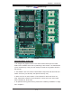
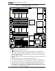
Chapter 1: Introduction Figure 1-1. X6QT8 Image Important Notes to the User 1. All images and graphics shown in this manual were based upon the latest PCB revision available at the time of publishing of this manual. The motherboard you've received may or may not look exactly the same as the graphics shown in this manual. 2. The X6QTE+ does not contain onboard SCSI components and dual PXH Controllers. It has only one PCI-Exp. slot (Slot 6: PCI-Exp. x16). 3.
X6QT8/X6QTE+ User's Manual Figure 1-2A.
Chapter 1: Introduction Quick Reference (X6QT8) Jumper Description Default Setting J27 Processor Speed Strapping Enable On (Enabled)(*Chpt.2) JBT1 CMOS Clear See Chapter 2 JFSB1 Front Side Bus Speed Select JP13 3rd Power Supply Fail Detect Off (200 MHz) Off (Disabled) JPA1 SCSI Controller Enable Pins 1-2 (Enabled) JPA2/JPA3 SCSI Chan.A/Chan.B Term.
X6QT8/X6QTE+ User's Manual LED Indicator Description DA1, DA2 Onboard SCSI Chan. A & Chan.
Chapter 1: Introduction Figure 1-2B.
X6QT8/X6QTE+ User's Manual Quick Reference (X6QTE+) Jumper Description Default Setting J27 Processor Speed Strapping Enable On (Enabled)(*Chpt.
Chapter 1: Introduction Motherboard Features CPU Latest CPU technology! • supports single, dual or quad 64-bit Intel® Xeon processor MP, 7000 Series and 7100 Series processors at front side bus speed of 800 or 677 MHz • supports the dual system bus architecture with increased bus speeds and bandwidth, especially designed or the 4-way server platform (*Note: The X6QTE+ supports up to 95W CPUs.
X6QT8/X6QTE+ User's Manual • Fan Status Monitor for fan speed/on-off control • VRM Protection Feature (880C, *980C, 1080C) (*Default: 980C) ACPI Power Features • Main switch override mechanism • Wake-on-Ring (WOR)/Wake-on-LAN (WOL) support • Power-on mode for AC power recovery • Chassis Intrusion LED Indicators • SCSI Activity LEDs (*X6QT8 only) • Power LED Software • IPMI 2.
Chapter 1: Introduction PROCESSOR#1 PCI EXP. B 1 PCI-X SLOT X8 CPU4 IMI B E8501 A PCI-EXPx16 SLOT PCI3 PROCESSOR#4 IMI A X4 PCI EXP. C VRM DDRII-400 XMB XMB DDRII-400 4 DDRII 400 DIMMs 4 DDRII 400 DIMMs X8 PCIEXP2 PCI-EXPx8 SLOT VRM DATA PXH #2 ADDR PCI EXP. D CPU3 CTRL PCI-X BUS(133 MHZ) B CPU2 ADD/DATA/CNTL PCI-X BUS(133 MHZ) PCI4 CTRL 1 PCI-X SLOT PROCESSOR#2 Gbit LAN Ophir 82571EB DATA ADDR VRM PROCESSOR#3 CPU1 ADD/DATA/CNTL VRM IMI C PCI EXP.
X6QT8/X6QTE+ User's Manual 1-2 Chipset Overview The E8501 Chipset Built upon the functionality and the capability of the E8501 chipset, the X6QT8/ X6QTE+ motherboard provides the performance and feature set required for 4-Way servers with configuration options optimized for communications, storage, computation or database applications. The Intel E8501 chipset is built around the E8501 chipset North Bridge (NB), and the Intel E8501 chipset external Bridge (XMB).
Chapter 1: Introduction 1-3 Special Features Recovery from AC Power Loss The feature allows the user to set the power state after a power outage. You can select Power-Off for the system power to remain off after a power loss. Select Power-On for the system power to be turned on after a power loss. Select Last State to allow the system to resume its last state before the power loss. The default setting is Last State.
X6QT8/X6QTE+ User's Manual Thermal Management/CPU VRM Overheat When the CPU reaches 700 C and above (Overheat), the CPU will go into throttling state. CPU Voltage will decrease to reduce CPU power consumption. When the CPU temperature reaches 780 C (*Default) and above, the Overheat LED and the Alarm Buzzer will be turned on in addition to the slowing down of the CPU. Once the CPU temperature returns to normal, the CPU voltage will return to normal as well, allowing the CPU to run at maximum speed.
Chapter 1: Introduction Main Switch Override Mechanism When an ATX power supply is used, the power button can function as a system suspend button to make the system enter a SoftOff state. The monitor will be suspended, and the hard drive will spin down. Pressing the power button again will cause the whole system to wake-up. During the SoftOff state, the ATX power supply provides power to keep the required circuitry in the system alive.
X6QT8/X6QTE+ User's Manual It is strongly recommended that you use a high quality power supply that meets ATX power supply Specification 2.01 or above. It must also be SSI compliant (-refer to the web site at http://www.ssiforum.org/ for details). Additionally, in areas where noisy power transmission is present, you may choose to install a line filter to shield the computer from noise. It is recommended that you also install a power surge protector to help avoid problems caused by power surges.
Chapter 2: Installation Chapter 2 Installation 2-1 Static-Sensitive Devices Electric-Static-Discharge (ESD) can damage electronic components. To ! prevent damage to your system board, it is important to handle it very carefully. The following measures are generally sufficient to protect your equipment from ESD. Precautions • Use a grounded wrist strap designed to prevent static discharge. • Touch a grounded metal object before removing the board from the antistatic bag.
X6QT8/X6QTE+ User's Manual 2-2 Processor and Heatsink Installation ! When handling the processor package, avoid placing direct pressure on the label area of the fan. Also, do not place the motherboard on a conductive surface which can damage the BIOS battery and prevent system bootup. IMPORTANT: Always connect the power cord last and always remove it before adding, removing or changing any hardware components.
Chapter 2: Installation Heatsink Installation ! IMPORTANT: Due to the weight of the Passive Heatsink (about 1KG), you need to have Heatsink Mounting plate installed on the chassis to prevent damage to the CPU and the motherboard) 1. Do not apply any thermal compound to Passive Heatsink the heatsink or the CPU die-the required amount has already been applied. 2. Place the heatsink on top of the CPU so that the four mounting holes are aligned with those on the retention mechanism. Screw#1 Screw#2 3.
X6QT8/X6QTE+ User's Manual To Un-install the Heatsink Caution! We do not recommend that you remove the CPU or heatsink. ! However, if you do need to un-install the heatsink, please follow the instructions below to uninstall the heatsink to prevent damage to the CPU or the CPU socket. 1. Unscrew and remove the heatsink screws from the motherboard in the sequence as show in the picture on the right. 2.
Chapter 2: Installation Figure 2-1. PGA604 Socket: Empty and with Processor Installed Empty socket Lever ! Warning! Make sure that you lift the lever completely when installing the CPU; otherwise, damage to the socket or CPU may occur. Triangle (Pin 1) Processor (installed) Triangle (Pin 1) (*Note: The CPU shown in the picture is for display only. Your CPU may or may not look exactly the same as the one shown in the picture above.
X6QT8/X6QTE+ User's Manual 2-3 Installing DIMMs CAUTION ! Exercise extreme care when installing or removing DIMM modules to prevent any possible damage. Also note that the memory is interleaved to improve performance. DIMM Installation (See Figure 2-2) 1. Insert the desired number of DIMMs into the memory slots, starting with the first DIMM of the first bank. Each UXMB chip is independent from each other, so memory modules can be installed on the first bank of a UXMB Controller.
Chapter 2: Installation To Remove: Use your thumbs to gently push near the edge of both ends of the module. This should release it from the slot. 2-4 Control Panel Connectors/IO Ports The I/O ports are color coded in conformance with the PC 99 specification. See Figure 2-3 below for the colors and locations of the various I/O ports. A. Back Panel Connectors/IO Ports SUPER ® X6QT8 2 4 1 3 5 6 7 Figure 2-3. Back Panel I/O Port Locations and Definitions Back Panel Connectors 1. Keyboard (Purple) 2.
X6QT8/X6QTE+ User's Manual B. Front Control Panel Front Control Panel JF1 contains header pins for various buttons and indicators that are normally located on a front control panel of the chassis. These connectors are designed specifically for use with Supermicro server chassis. See Figure 2-4 for the descriptions of the various control panel buttons and LED indicators. Refer to the following section for descriptions and pin definitions. Figure 2-4.
Chapter 2: Installation C. Front Control Panel Pin Definitions NMI Button NMI Button Pin Definitions (JF1) The non-maskable interrupt button header is located on pins 19 and 20 of JF1. Refer to the table on the right for pin definitions. Power LED Pin# Definition 19 Control 20 Ground Power LED Pin Definitions (JF1) The Power LED connection is located on pins 15 and 16 of JF1. Refer to the table on the right for pin definitions. Pin# Definition 15 +5V 16 Ground A. NMI B.
X6QT8/X6QTE+ User's Manual HDD LED HDD LED Pin Definitions (JF1) The HDD LED connection is located on pins 13 and 14 of JF1. Attach a Pin# Definition hard drive LED cable here to display a hard disk drive activity (including 13 +5V 14 HD Active SCSI, Serial ATA and IDE). See the table on the right for pin definitions.
Chapter 2: Installation Overheat/Fan Fail LED OH/Fan Fail LED Pin Definitions (JF1) Connect an LED to the OH/Fan Fail LED connection on pins 7 and 8 of JF1 to provide an advanced warning of chassis overheating and fan failure. OH/Fan Fail Indicator Status Pin# Definition State 7 Vcc Off Normal 8 Ground On Overheat Flashing Fan Fail Refer to the table on the right for pin Definition definitions.
X6QT8/X6QTE+ User's Manual Reset Button Reset Button Pin Definitions (JF1) The Reset Button connection is located on pins 3 and 4 of JF1. Attach Pin# Definition it to the hardware reset switch on the computer case. Refer to the table on 3 Reset 4 Ground the right for pin definitions. Power Button Power Button Pin Definitions (JF1) The Power Button connection is located on pins 1 and 2 of JF1. Momentarily contacting both pins will power on/off the system.
Chapter 2: Installation 2-5 Connecting Cables ATX Power Connector ATX Power 24-pin Connector Pin Definitions There is a 24-pin main power supply connector (JPW1) and two 8-pin CPU PWR connectors (JPW2/JPW3) on the board. This power connector meets the SSI EPS 12V specification. See the table on the right for pin definitions. For CPU PWR (JPW2/JPW3), please refer to the item listed below.
X6QT8/X6QTE+ User's Manual Chassis Intrusion Chassis Intrusion Pin Definitions (JL1) A Chassis Intrusion header is located at JL1. Attach an appropriate cable to inform you of a chassis intrusion.
Chapter 2: Installation Wake-On-LAN Wake-On-LAN Pin Definitions (JWOL) The Wake-On-LAN header is designated JWOL on the motherboard. See the table on the right for pin definitions. (You must also have a LAN card Pin# Definition 1 +5V Standby with a Wake-On-LAN connector and 2 Ground cable to use this feature.) 3 Wake-up Wake-On-Ring The Wake-On-Ring header is designated JWOR. This function allows your computer to receive and to be "woken by" an incoming call to the modem when in suspend state.
X6QT8/X6QTE+ User's Manual Serial Ports Serial Port Pin Definitions (COM1/COM2) There are one Serial Port-COM1 Pin # (JCOM1) and one Serial HeaderCOM2 (JCOM2) on the motherboard. The Serial Header located at JCOM2 can be accessed from the front panel. See the table on the right for pin definitions. Definition Pin # Definition 1 CD 6 DSR 2 RD 7 RTS 3 TD 8 CTS 4 DTR 9 RI 5 Ground 10 NC Note: Pin 10 is included on the header but not on the port. NC indicates no connection.
Chapter 2: Installation ATX PS/2 Keyboard and PS/2 Mouse Ports PS/2 Keyboard and Mouse Port Pin Definitions The ATX PS/2 keyboard and PS/2 Pin# Definition mouse are located at JKM1 on the I/O 1 Data Backplane. See the table on the right for pin definitions. 2 NC 3 Ground 4 VCC 5 Clock 6 NC Fan Headers Fan Header Pin Definitions There are nine fan headers (Fan 1 to Fan 9) on the motherboard. These Fans are CPU and system cooling fans. See the table on the right for pin definitions.
X6QT8/X6QTE+ User's Manual VGA Connector A VGA connector (JVGA1) is located next to the GLAN1 on the IO backplane. Refer to the board layout below for the location. Power Supply Failure PWR Fail Pin Definitions Connect a cable from your power supply to the J3P1 header to provide a warning of power supply failure. This warning signal is passed through the PWR_LED pin to indicate of a power failure on the chassis. See the table on the right for pin definitions.
Chapter 2: Installation SMB Header SMB Header Pin Definitions A System Management Bus header is located at J22. Connect the appropriate cable here to utilize SMB on your system. Pin# Definition 1 Data 2 Ground 3 Clock 4 No Connection SMB Power (I2 C) PWR SMB Pin Definitions Connector I2 C Connector (PSSMB), located next to the IDE#2 Connector, monitors onboard power supply, fan and system temperatures.
X6QT8/X6QTE+ User's Manual Power LED/Speaker (JD1) Speaker Connector On the JD1 header, pins 1-3 are for a power LED and pins 4-7 are for the speaker. See Pin Setting the table on the right for speaker pin definitions. *Note: The speaker connector pins Definition Pins 6-7 Internal Speaker Pins 4-7 External Speaker are for use with an external speaker. If you wish to use the onboard speaker, you should close pins 6-7 with a jumper.
Chapter 2: Installation JTAG Connector JTAG Connector JTAG Connector located next to the IDE2 connector allows you to configure the onboard CPLD (-Complex Programmable Logic Device.) See the table on the right for pin definitions. Alarm Reset (JAR1) The system will notify you in the event of a power supply failure. This feature is only available for chassis with Supermicro redundant power supply units installed.
X6QT8/X6QTE+ User's Manual 2-6 Jumper Settings Explanation of Jumpers Connector Pins 3 2 1 3 2 1 To modify the operation of the motherboard, jumpers can be used to choose between optional settings. Jumpers create shorts between two Jumper Cap pins to change the function of the connector. Pin 1 is identified with a Setting square solder pad on the printed circuit Pin 1-2 short board. See the motherboard layout pages for jumper locations.
Chapter 2: Installation CMOS Clear JBT1 is used to clear CMOS. Instead of pins, this "jumper" consists of contact pads to prevent the accidental clearing of CMOS. To clear CMOS, use a metal object such as a small screwdriver to touch both pads at the same time to short the connection. Always remove the AC power cord from the system before clearing CMOS. Note: For an ATX power supply, you must completely shut down the system, remove the AC power cord and then short JBT1 to clear CMOS.
X6QT8/X6QTE+ User's Manual VGA Enable/Disable VGA Enable/Disable Jumper Settings JPG1 enables or disables the VGA Connector on the motherboard. See the Jumper Setting table on the right for jumper settings. Pins 1-2 (*Default) Enabled* Pins 2-3 Disabled FSB Speed Select FSB Jumper Settings Front Side Bus Speed Select Jumper located at JFSB1 allows you to set the FSB speed. See the table on the right for jumper settings.
Chapter 2: Installation SCSI Controller Enable/ Disable (*For X6QT8 only) SCSI Enable/Disable Jumper Settings Jumper JPA1 allows you to enable or Jumper Setting disable the SCSI Controller. The default Pins 1-2 (*Default) Enabled Pins 2-3 Disabled setting is pins 1-2 to enable the SCSI Controller. See the table on the right Definition for jumper settings.
X6QT8/X6QTE+ User's Manual 3rd PWR Supply PWR Failure Detect (JP13) This function allows the system to no- 3rd PWR Supply PWR Fault Jumper Settings tify you in the event of a power supply Jumper Setting failure. This feature assumes that three power supply units are installed in the chassis, with one acting as a backup. If Definition Closed Enabled Open (*Default) Disabled* you only have one or two power supply units installed, you should disable this jumper to prevent false alarms.
Chapter 2: Installation 2-7 Left Onboard Indicators Right GLAN LEDs There are two Gigabit Ethernet LAN ports GLAN Left LED Connection Speed Indicator (located beside the Video port) on the motherboard. Each GLAN port has two LEDs. The blinking Amber LED indicates activity while the other LED may be green, amber or off to indicate the speed of the LED Color Definition Off 10Mbps or No Connection Green 100 Mbps Amber 1 Gbps GLAN Right LED Activity Indicator connection.
X6QT8/X6QTE+ User's Manual SCSI Channel Indicators (DA1, DA2) (*X6QT8 only) There are two SCSI Channel Status LEDs (DA1, DA2) on the motherboard. DA1 indicates the SCSI Channel A activity, and DA 2, Channel B. See the layout below for DA1 and DA2 locations. Onboard Power LED (LE1) Onboard PWR LED Indicator (LE1) There is an Onboard Power LED (LE1) located on the motherboard. When LE1 is off, the system is off. When the green light is on, the system is on. See the layout below for the LED location.
Chapter 2: Installation 2-8 Floppy, IPMI, Hard Disk Drive and SCSI Connections Note the following when connecting the floppy and hard disk drive cables: • The floppy disk drive cable has seven twisted wires. • A red mark on a wire typically designates the location of pin 1. • A single floppy disk drive ribbon cable has two connectors to provide for two floppy disk drives.
X6QT8/X6QTE+ User's Manual IDE Connectors IDE Drive Connectors Pin Definitions (IDE) There are no jumpers to configure Pin# Definition the onboard IDE#1 and IDE #2. 1 Reset IDE 2 Ground 3 Host Data 7 4 Host Data 8 5 Host Data 6 6 Host Data 9 pact card is used, you will need to 7 Host Data 5 8 Host Data 10 connect a power cable to its power 9 Host Data 4 10 Host Data 11 connector to provide adequate 11 Host Data 3 12 Host Data 12 power to the drive. (JWF1: IDE#1, JWF2: IDE#2.
Chapter 2: Installation Ultra320 SCSI Connectors (*X6QT8 Only) Ultra320 SCSI Drive Connector Pin Definitions Refer to the table below for the pin definitions of the Ultra320 SCSI connectors: SCSI Channel A (located at JA1) and SCSI Channel B (located at JA2.) IPMI 2.0 Socket An IPMI 2.0 Socket is located on the motherboard. Refer to the layout below for the IPMI Socket location.
X6QT8/X6QTE+ User's Manual Notes 2-32
Chapter 3: Troubleshooting Chapter 3 Troubleshooting 3-1 Troubleshooting Procedures Use the following procedures to troubleshoot your system. If you have followed all of the procedures below and still need assistance, refer to the ‘Technical Support Procedures’ and/or ‘Returning Merchandise for Service’ section(s) in this chapter. *Note: Always disconnect the power cord before adding, changing or installing any hardware components. Before Power On 1.
X6QT8/X6QTE+ User's Manual 2. The battery on your motherboard may be old. Check to verify that it still supplies ~3VDC. If it does not, replace it with a new one. 3. If the above steps do not fix the Setup Configuration problem, contact your vendor for repairs. NOTE If you are a system integrator, VAR or OEM, a POST diagnostics card is recommended. For I/O port 80h codes, refer to Appendix B. Memory Errors 1. Make sure that all DIMM modules are properly and fully installed. 2.
Chapter 3: Troubleshooting 3. If you still cannot resolve the problem, include the following information when contacting Super Micro for technical support: • Motherboard model and PCB revision number • BIOS release date/version (this can be seen on the initial display when your system first boots up) •System configuration An example of a Technical Support form is on our web site at http://www. supermicro.com/support/contact.cfm/. 4.
X6QT8/X6QTE+ User's Manual 3-4 Returning Merchandise for Service A receipt or copy of your invoice marked with the date of purchase is required before any warranty service will be rendered. You can obtain service by calling your vendor for a Returned Merchandise Authorization (RMA) number. When returning to the manufacturer, the RMA number should be prominently displayed on the outside of the shipping carton, and mailed prepaid or hand-carried.
Chapter 4: AMI BIOS Chapter 4 AMIBIOS 4-1 Introduction This chapter describes the AMIBIOS Setup Utility for the X6QT8/X6QTE+. The AMI ROM BIOS is stored in a Flash EEPROM and can be easily updated using a floppy disk-based program. This chapter describes the basic navigation of the AMIBIOS Setup Utility setup screens. Starting BIOS Setup Utility To enter the AMIBIOS Setup Utility screens, hit the key while the system is booting up.
X6QT8/X6QTE+ User’s Manual 4-2 Main Setup When you first enter the AMI BIOS Setup Utility, you will enter the Main setup screen. You can always return to the Main setup screen by selecting the Main tab on the top of the screen. The Main BIOS Setup screen is shown below.
Chapter 4: AMI BIOS 4-3 Advanced Settings The Advanced Settings screen and sub menus are listed below: Warning When you first enter the Advanced Setup screen, the Setup Warning will be displayed. Please follow the instruction and set the correct value for each item to prevent the system from malfunctioning. CPU Configuration Sub-Menu Configure Advanced CPU Settings This option allows the user to configure the Advanced CPU settings for the processor(s) installed in the system.
X6QT8/X6QTE+ User’s Manual Adjacent Cache Line Prefetch (*Available when supported by the OS and the CPU.) The CPU fetches the cache line for 64 bytes if this option is set to Disabled. The CPU fetches both cache lines for 128 bytes as comprised if Enabled. The options are Disabled and Enabled. Max CPUID Value Limit This feature allows the user to set the maximum CPU ID value. Enable this function to boot the legacy operating systems that cannot support processors with extended CPUID functions.
Chapter 4: AMI BIOS C1 Configuration Mode (*Available when supported by the CPU.) Select Standard to enable the C1 Halt State to partially turn off the CPU internal clocks to conserve energy and prevent system overheating when the OS is idle. Select Enhanced to enable the Enhanced C1 Halt State to lower the CPU clock frequency and the supply voltage before turning off the clocks.
X6QT8/X6QTE+ User’s Manual PIO Mode The IDE PIO (Programmable I/O) Mode programs timing cycles between the IDE drive and the programmable IDE controller. As the PIO mode increases, the cycle time decreases. The options are Auto, 0, 1, 2, 3, and 4. Select Auto to allow the AMI BIOS to automatically detect the PIO mode. Use this value if the IDE disk drive support cannot be determined. Select 0 to allow the AMI BIOS to use PIO mode 0. It has a data transfer rate of 3.3 MBs.
Chapter 4: AMI BIOS 32-Bit Data Transfer Select Enabled to activate the function of 32-Bit data transfer. Select "Disabled" to disable this function. The options are Enabled and Disabled. Hard Disk Write Protect Select Enabled to enable the function of Hard Disk Write Protect to prevent data from being written to HDD. The options are Enabled or Disabled. IDE Detect Time Out This feature allows the user to set the time-out value for detecting ATA, ATA PI devices installed in the system.
X6QT8/X6QTE+ User’s Manual Allocate IRQ to PCI VGA Set this value to allow or restrict the system from giving the VGA adapter card an interrupt address. The options are Yes and No. Palette Snooping Select Enabled to inform the PCI devices that an ISA graphics device is installed in the system in order for the graphics card to function properly. The options are Enabled and Disabled. PCI IDE BusMaster Set this value to allow or prevent the use of PCI IDE busmastering.
Chapter 4: AMI BIOS Advanced Chipset Settings This item allows the user to configure the Advanced Chipset settings for the system. NorthBridge Configuration This feature allows the user to configure the settings for the Intel E7520 NorthBridge chipset. Memory Remap Feature Select Enabled to allow remapping of the overlapped PCI memory above the total physical memory. The options are Enabled and Disabled. Max.
X6QT8/X6QTE+ User’s Manual APCI Configuration This item allows the user to enable or disable the ACPI support for the operating system. ACPI OS Select Yes to enable ACPI support for your operating system. The options are Yes and No. Advanced ACPI Configuration Use this feature to configure additional ACPI options. Select Yes if the operating system supports ACPI. Select No if the operating system does not support ACPI. The options are No and Yes. ACPI 2.
Chapter 4: AMI BIOS Hardware Health Configuration This feature allows the AMI BIOS to automatically display the status of the following items: Temperatures CPU Overheat Temperature This feature allows the user to set the CPU Overheat temperature threshold. The options range from 65oC to 90oC. Use the <+> and <-> keys to set the desired setting. The default setting is 78oC.
X6QT8/X6QTE+ User’s Manual MPS Configuration This section allows the user to configure the multiprocessors table. MPS Revision This feature allows the user to select the MPS Revision. Please follow the instructions given on the screen to select the MPS Revision Number. The options are 1.1 and 1.4. PCI Express Configuration This section allows the user to configure the PCI Express slots.
Chapter 4: AMI BIOS SMBIOS Configuration SMBIOS SMI Support Select Enabled to enable the function of SMBIOS SMI Wrapper support for PnP Func 50h-54h. The options are Enabled and Disabled. Remote Access Configuration You can use this screen to select options for the Remote Access Configuration. Use the up and down arrow keys to select an item. Use the <+> and <-> keys to change the value of the selected option. Remote Access This feature allows the user to enable the function of Remote Access.
X6QT8/X6QTE+ User’s Manual Terminal Type This feature allows the user to select the target terminal type for Console Redirection.The options are ANSI, VT100, and VT-UTF8. VT-UTF8 Comb Key Support This feature allows the user to select Enabled to enable the VT-UTF8 Combination Key support for the ANSI/VT100 Terminals. The options are Enabled and Disabled. Sredir Memory Display Delay This feature allows the user to decide how many seconds the BIOS shall wait before memory information is displayed.
Chapter 4: AMI BIOS BIOS Settings Configuration Quick Boot If Enabled, this option will skip certain tests during POST to reduce the time needed for system bootup. The options are Enabled and Disabled. Quiet Boot This option allows the boot up screen options to be modified between POST messages or the OEM logo. Select Disabled to allow the computer system to display the POST messages. Select Enabled to allow the computer system to display the OEM logo.
X6QT8/X6QTE+ User’s Manual Watch Dog Timer If enabled, this option will automatically reset the system if the system is not active for more than 5 minutes. The options are Enabled and Disabled. Resume On Modem Ring Select On to “wake your system up” when an incoming call is received by your modem. The options are On and Off. Restore on AC Power Loss The feature allows the user to set the power state after a power outage. Select Power-Off for the system power to remain off after a power loss.
Chapter 4: AMI BIOS Boot Device Priority This feature allows the user to specify the sequence of priority for the Boot Device. The settings are 1st Floppy Drive, CD ROM, ATAPI CDROM and Disabled.
X6QT8/X6QTE+ User’s Manual 4-5 Security Settings The AMI BIOS provides a Supervisor and a User password. If you use both passwords, the Supervisor password must be set first. Change Supervisor Password Select this option and press to access the sub-menu, and then type in the password. Change User Password Select this option and press to access the sub-menu, and then type in the password.
Chapter 4: AMI BIOS 4-6 Exit Options Select the Exit tab from the AMIBIOS Setup Utility screen to enter the Exit BIOS Setup screen. Saving Changes and Exit When you have completed the system configuration changes, select this option to leave the BIOS Setup and reboot the computer, so the new system configuration parameters can take effect. Select Save Changes and Exit from the Exit menu and press .
X6QT8/X6QTE+ User’s Manual Load Fail-Safe Defaults To set this feature, select Load Fail-Safe Defaults from the Exit menu and press . The Fail-Safe settings are designed for maximum system stability, but not for maximum performance.
Appendix A: AMIBIOS Error Beep Codes Appendix A BIOS Error Beep Codes During the POST (Power-On Self-Test) routines, which are performed each time the system is powered on, errors may occur. Non-fatal errors are those which, in most cases, allow the system to continue the boot-up process. The error messages normally appear on the screen. Fatal errors are those which will not allow the system to continue the boot-up procedure.
X6QT8/X6QTE+ User’s Manual Notes A-2
Appendix B: BIOS POST Checkpoint Codes Appendix B BIOS POST Checkpoint Codes When AMIBIOS performs the Power On Self Test, it writes checkpoint codes to I/O port 0080h. If the computer cannot complete the boot process, diagnostic equipment can be attached to the computer to read I/O port 0080h. B-1 Uncompressed Initialization Codes The uncompressed initialization checkpoint codes are listed in order of execution: Checkpoint Code Description D0h The NMI is disabled. Power on delay is starting.
X6QT8/X6QTE+ User's Manual B-2 Bootblock Recovery Codes The bootblock recovery checkpoint codes are listed in order of execution: Checkpoint Code Description E0h The onboard floppy controller if available is initialized. Next, beginning the base 512 KB memory test. E1h Initializing the interrupt vector table next. E2h Initializing the DMA and Interrupt controllers next. E6h Enabling the floppy drive controller and Timer IRQs. Enabling internal cache memory. Edh Initializing the floppy drive.
Appendix B: BIOS POST Checkpoint Codes B-3 Uncompressed Initialization Codes The following runtime checkpoint codes are listed in order of execution. These codes are uncompressed in F0000h shadow RAM. Checkpoint Code Description 03h The NMI is disabled. Next, checking for a soft reset or a power on condition. 05h The BIOS stack has been built. Next, disabling cache memory. 06h Uncompressing the POST code next. 07h Next, initializing the CPU and the CPU data area.
X6QT8/X6QTE+ User's Manual Checkpoint Code Description 25h Interrupt vector initialization is done. Clearing the password if the POST DIAG switch is on. 27h Any initialization before setting video mode will be done next. 28h Initialization before setting the video mode is complete. Configuring the monochrome mode and color mode settings next. 2Ah Bus initialization system, static, output devices will be done next, if present. See the last page for additional information.
Appendix B: BIOS POST Checkpoint Codes Checkpoint Code Description 4Ch The memory below 1 MB has been cleared via a soft reset. Clearing the memory above 1 MB next. 4Dh The memory above 1 MB has been cleared via a soft reset. Saving the memory size next. Going to checkpoint 52h next. 4Eh The memory test started, but not as the result of a soft reset. Displaying the first 64 KB memory size next. 4Fh The memory size display has started. The display is updated during the memory test.
X6QT8/X6QTE+ User's Manual Checkpoint Code Description 86h The password was checked. Performing any required programming before WINBIOS Setup next. 87h The programming before WINBIOS Setup has completed. Uncompressing the WINBIOS Setup code and executing the AMIBIOS Setup or WINBIOS Setup utility next. 88h Returned from WINBIOS Setup and cleared the screen. Performing any necessary programming after WINBIOS Setup next. 89h The programming after WINBIOS Setup has completed.
Appendix B: BIOS POST Checkpoint Codes Checkpoint Code Description A9h Returned from adaptor ROM at E000h control. Performing any initialization required after the E000 option ROM had control next. Aah Initialization after E000 option ROM control has completed. Displaying the system configuration next. Abh Uncompressing the DMI data and executing DMI POST initialization next. B0h The system configuration is displayed. B1h Copying any code to specific areas.
X6QT8/X6QTE+ User's Manual Notes B-8
Appendix C: Software Installation Appendix C Software Installation After all the hardware has been installed, you must first configure the Adaptec Embedded Serial ATA RAID Driver before you install the Windows operating system. The necessary drivers are all included on the Supermicro bootable CDs that came packaged with your motherboard. C-1 Introduction to the Adaptec Embedded Serial ATA RAID Controller Driver Serial ATA (SATA) Serial ATA(SATA) is a physical storage interface.
X6QT8/X6QTE+ User's Manual *Non-Combined Mode: Parallel ATA only: with the maximum of 4 devices supported; *Non-Combined Mode: Serial ATA only: with the maximum of 2 devices supported; *Combined Mode: SATA devices and PATA: with the support of 2 devices each (total: 4 devices maximum). (For IDE/SATA configurations, please refer to the table below.) To configure SATA RAID for Operating Systems that support RAID functions(--Windows, Red Hat & SuSe, Linux) 1. Select "Advanced Setting" from the AMI BIOS menu. 2.
Appendix C: Software Installation Using the Adaptec RAID Configuration Utility (ARC) The Adaptec RAID Configuration Utility is an embedded BIOS Utility, including: *Array Configuration Utility: Use this utility when you want to create, configure and manage arrays. * Disk Utilities: Use this option to format or verify disks.
X6QT8/X6QTE+ User's Manual Managing Arrays Select this option to view array properties, and delete arrays. The following sections describe the operations Of "Managing Arrays". To select this option, use the arrow keys and the key to select "Managing Arrays" from the main menu (as shown above).
Appendix C: Software Installation Viewing Array Properties To view the properties of an existing array: 1. At the BIOS prompt, press Ctrl+A. 2. From the ARC menu, select Array Configuration Utility (ACU). 3. From the ACU menu, select Manage Arrays (as shown on the previous screen.) 4. From the List of Arrays dialog box, select the array you want to view and press Enter. The Array Properties dialog box appears, showing detailed information on the array.
X6QT8/X6QTE+ User's Manual Creating Arrays Before creating arrays, make sure the disks for the array are connected and installed in your system. Note that disks with no usable space, or disks that are un-initialized are shown in gray and cannot be used. See Initializing Disk Drives. To create an array: 1 Turn on your computer and press Ctrl+A when prompted to access the ARC utility. 2 From the ARC menu, select Array Configuration Utility Main Menu (ACU) (as shown on the first screen on page C-5).
Appendix C: Software Installation 5 Press Enter when both disks for the new array are selected. The Array Properties menu displays (as the screen shown below). Assigning Array Properties Once you've create a new array, you are ready to assign the properties to the array. *Caution: Once the array is created and its properties are assigned, you cannot change the array properties using the ACU. You will need to use the Adaptec Storage Manager - Browser Edition.
X6QT8/X6QTE+ User's Manual 2. Under the item "Arrays Label", type in an label and press Enter. (*Note: The label shall not be more than 15 characters.) 3. For RAID 0, select the desired stripe size. (*Note: Available stripe sizes are 16, 32, and 64 KB-default. It is recommended that you do not change the default setting.) 4. The item: "Create RAID via" allows you to select between the different creating methods for RAID 0 and RAID 1. The following table gives examples of when each is appropriate.
Appendix C: Software Installation 5. When you are finished, press Done (as the screen shown below). Notes: 1. Before adding a new drive to an array, back up any data contained on the new drive. Otherwise, all data will be lost. 2. If you stop the Build or Clear process on a RAID 1 from ACU, you can restart it by pressing Ctrl+R. 3. A RAID 1 created using the Quick Init option may return some data mis-compares if you later run a consistency check. This is normal and is not a cause for concern. 4.
X6QT8/X6QTE+ User's Manual Adding a Bootable Array To make an array bootable: 1. From the Main menu, select Manage Arrays. 2. From the List of Arrays, select the array you want to make bootable, and press Ctrl+B. 3. Enter Y to create a bootable array when the following message is displayed: "This will make all other existing bootable array non-bootable. Do you want to make this array bootable? (Yes/No):" Then, a bootable array will be created.
Appendix C: Software Installation Initializing Disk Drives If an installed disk does not appear in the disk selection list for creating a new array, or if it appears grayed out, you may have to initialize it before you can use it as part of an array. Drives attached to the controller must be initialized before they can be used in an array. Caution: Initializing a disk overwrites the partition table on the disk and makes any data on the disk inaccessible.
X6QT8/X6QTE+ User's Manual 4. Use the up and down arrow keys to highlight the disk you wish to initialize and press Insert (as shown in the screen below).
Appendix C: Software Installation 5. Repeat Step 4 so that both drives to be initialized are selected (as shown in the screen below). 6. Press Enter. 7. Read the warning message as shown in the screen. 8. Make sure that you have selected the correct disk drives to initialize. If correct, type Y to continue.
X6QT8/X6QTE+ User's Manual Rebuilding Arrays *Note 1: Rebuilding applies to Fault Tolerant array (RAID 1) only. If an array Build process (or initialization) is interrupted or critical with one member missing, you must perform a Rebuild to get the array to Optimal status. For a critical array Rebuild operation, the optimal drive is the source drive. *Note 2: If no spare array exists and a hard disk drive fails, you need to create a spare before you can rebuild an array.
Appendix C: Software Installation Using the Disk Utilities The Disk Utilities enable you to format or verify the media of your Serial ATA hard disks. To access the disk utilities: 1. Turn on your computer and press Ctrl+A when prompted to access the ARC utility (as shown in the screen below.
X6QT8/X6QTE+ User's Manual 2. From the ARC menu, select Disk Utilities as shown in the screen below. 3 Select the desired disk and press Enter (as shown in the screen below.
Appendix C: Software Installation You can choose from the following options: 1. Format Disk—Simulates a low-level format of the hard drive by writing zeros to the entire disk. Serial ATA drives are low-level formatted at the factory and do not need to be low-level formatted again. (*Caution: Formatting destroys all data on the drive. Be sure to back up your data before performing this operation.) 2. Verify Disk Media—Scans the media of a disk drive for defects. To Exit Adaptec RAID Configuration Utility 1.
X6QT8/X6QTE+ User's Manual C-2 Installing Intel's ICH5R Driver by Adaptec and the Windows OS a. Insert Supermicro's bootable CD that came with the package into the CD Drive during the system reboot, and the screen:"Super Micro Driver Diskette Maker" will appear. b. From the list displayed on the screen, choose the item: "Intel ICH5R Driver by 3rd Party (Adaptec)" and press . c. From the next screen displayed, choose the OS driver you want to install and press . d.
Appendix C: Software Installation C-3 Installing Other Software Programs and Drivers Installing Drivers other than the Adaptec Embedded Serial ATA RAID Controller Driver After you've installed Windows Operating System, a screen as shown below will appear. You are ready to install software programs and drivers that have not yet been installed. To install these software programs and drivers, click the icons to the right of these items.
X6QT8/X6QTE+ User's Manual Supero Doctor III The Supero Doctor III program is a Web base management tool that supports remote management capability. It includes Remote and Local Management tools. The local management is called SD III Client. The Supero Doctor III program included on the CDROM that came with your motherboard allows you to monitor the environment and operations of your system. Supero Doctor III displays crucial system information such as CPU temperature, system voltages and fan status.
Appendix C: Software Installation Supero Doctor III Interface Display Screen-II (Remote Control) (*Note: SD III Software Revision 1.0 can be downloaded from our Web site at: ftp://ftp.supermicro.com/utility/Supero_Doctor_III/. You can also download SDIII User's Guide at: http://www.supermicro.com/PRODUCT/Manuals/SDIII/UserGuide. pdf. For Linux, we will still recommend Supero Doctor II.
X6QT8/X6QTE+ User's Manual Notes C-22