
User's and BIOS Manual (1.1a)


Chapter 2: Installation
2-23
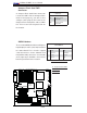
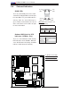
LAN1/2
®
S
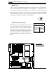
UPER X7DA8+
Fan1
8-pin PWR
FP ControlSPK
PW LED
JOH1
Fan3
IDE1
Floppy
320 SCSI Channel A
Fan4
SATA3
SATA5
USB4/5
SMB
PCI-X 100 MHz ZCR (Green Slot)
PCI-X 133 MHz
JWD
Battery
GLAN
CTLR
JPG1
PCI-Exp x4
North Bridge
COM1
Fan6
Fan5
ATX PWR
4-Pin
PWR
J3P
24-Pin
SCSI CTRL
PXH
CPU1
CPU2
South Bridge
Fan7
JAR
J17
PSF
Fan2
Compact Flash
LE1
Fan8
JCF1
JWF1
JPA2
JPA3
JPA1
320 SCSI Channel B
SATA2
SATA4
SATA1
SATA0
JL1
PCI-X 133 MHz
JPL2
PCI-33MHz
FP Audio
PCI-Exp x16
SIM LP IPMI
DIMM 1A (Bank 1)
DIMM 1B (Bank 1)
DIMM 2A (Bank 2)
DIMM 2B (Bank 2)
DIMM 3A (Bank 3)
DIMM 3B (Bank 3)
DIMM 4A (Bank 4)
DIMM 4B (Bank 4)
JWOL
JWOR
KB/
Mouse
USB 0/
1/2/3
JI
2
C2
JI
2
C3
JI
2
C4
5000X
BIOS
DA1
DA2
CPU
Fan 1
CD1
JPL1
JI
2
C1
CPU
Fan2
HD
Audio
SGPIO1
SGPIO2
Parrallel
Port
Audio
CTRL
S I/O
J8
Clear
CMOS
ESB
Cha.
Intru.
A
B
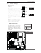
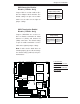
A. BP HD Audio
B. FP Accessible Audio
C. CD1
C
CD1 Pin Defi ni-
tion
Pin# Defi nition
1 Left
2 Ground
3 Ground
4 Right
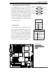
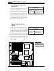
High Defi nition Audio (HD Audio)
The X7DA8+/E+ features a 7.1+2 Channel
High Definition Audio (HDA) (JC1) codecs
that provide 10DAC channels, simultaneously
supporting 7.1 sound playback with 2 channels
of independent stereo sound output (multiple
streaming) through the front panel stereo out
for front L&R, rear L&R, center and subwoofer
speakers. Use the Advanced software included
in the CD-ROM with your motherboard to
enable this function.
FP Audio Pin Defi nition
Pin# Defi nition
1 Right Stereo
Signal
2 Ground
3 Ground
4 Left Stereo Signal
Grey: Side
Surround
Black: Back
Surround
Orange:
CEN/LFE
Pink: Mic-In
Green:Front
Blue: Line-In
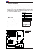
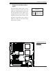
CD Headers
There is a 4-pin CD header (CD1) and a Front
Pane Accessible Audio header (JC2) on the
motherboard. These headers allow you to use
the onboard sound for audio CD playback.
(See the next page for details on FP Audio.)
Connect an audio cable from your CD drive to
the CD header that fi ts your cable's connector.
Only one CD header can be used at a time.
See the tables at right for pin defi nitions.