X7DAL-E+ USER’S MANUAL Revision 1.
The information in this User’s Manual has been carefully reviewed and is believed to be accurate. The vendor assumes no responsibility for any inaccuracies that may be contained in this document, makes no commitment to update or to keep current the information in this manual, or to notify any person or organization of the updates. Please Note: For the most up-to-date version of this manual, please see our web site at www.supermicro.com. Super Micro Computer, Inc.
Preface Preface About This Manual This manual is written for system integrators, PC technicians and knowledgeable PC users. It provides information for the installation and use of X7DAL-E+ motherboard. The X7DAL-E+ supports dual the Intel Quad-Core and Dual-Core processors with a front side bus speed of 1.333 GHz/1.066 GHz/667 MHz.
X7DAL-E+ User's Manual Table of Contents Preface About This Manual ...................................................................................................... iii Manual Organization ................................................................................................... iii Conventions Used in the Manual .................................................................................. iii Chapter 1: Introduction 1-1 Overview ........................................................
Table of Contents Reset Button .......................................................................................... 2-13 Power Button .......................................................................................... 2-13 2-5 Connecting Cables ......................................................................................... 2-14 ATX Power Connector .......................................................................... 2-14 Processor Power Connector .................................
X7DAL-E+ User's Manual PCI-U Universal Slot ............................................................................... 2-32 IDE Connectors ........................................................................................ 2-33 Chapter 3: Troubleshooting 3-1 Troubleshooting Procedures ........................................................................... 3-1 Before Power On....................................................................................... 3-1 No Power...................
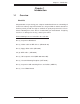
Chapter 1: Introduction Chapter 1 Introduction 1-1 Overview Checklist Congratulations on purchasing your computer motherboard from an acknowledged leader in the industry. Supermicro boards are designed with the utmost attention to detail to provide you with the highest standards in quality and performance. Check that the following items have all been included with your motherboard. If anything listed here is damaged or missing, contact your retailer.
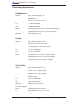
X7DAL-E+ User's Manual Contacting Supermicro Headquarters Address: Super Micro Computer, Inc. 980 Rock Ave. San Jose, CA 95131 U.S.A. Tel: +1 (408) 503-8000 Fax: +1 (408) 503-8008 Email: marketing@supermicro.com (General Information) support@supermicro.com (Technical Support) Web Site: www.supermicro.com Europe Address: Super Micro Computer, B.V. Het Sterrenbeeld 28, 5215 ML 's-Hertogenbosch, The Netherlands Tel: +31 (0) 73-6400390 Fax: +31 (0) 73-6416525 Email: sales@supermicro.
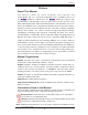
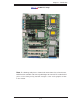
Chapter 1: Introduction X7DAL-E+ Image Note: The drawings and pictures shown in this manual were based on the latest PCB Revision available at the time of publishing of the manual. The motherboard you’ve received may or may not look exactly the same as the graphics shown in the manual.
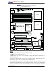
X7DAL-E+ User's Manual Fan1 X7DAL-E+ Motherboard Layout (not drawn to scale) 4-Pin 8-Pin PWR 24-Pin ATX PWR PWR JPW1 I2C JPW3 JPW2 PWR JP I2C JPF PWR JPWF JP3 Force-On Alarm JP5 Reset KB/ Mouse JKM1 USB 0/1/2/3 LE2 JUSB3 J9B1 DIMM 4A (Bank 4) J8B2 DIMM 3A (Bank 3) J8B1 DIMM 2B (Bank 2) J7B3 DIMM 2A (Bank 2) J7B2 DIMM 1B (Bank 1) J7B1 DIMM 1A (Bank 1) COM1 JCOM1 2nd Branch 1st Branch COM2 JCOM3 CPU1 LAN1/LAN2 JLAN1 SUPER X7DAL-E+ Fan5 J2 Fan6 LAN CTRLR J5 5000X North Bridge Slo
Chapter 1: Introduction Quick Reference (X7DAL-E+) (See Chapter 2 for details) Jumper Description Default Setting JBT1 CMOS Clear See Chapter 2 JI C1/JI C2 SMB to PCI Slot#1/Slot#2 Speed Pins 2-3 (Disabled) JPAC1 Audio Enable Pins 1-2 (Enabled) JPF JPL1/ JPL2 PWR Force-On GLAN1/GLAN2 Enable Off (Normal) Pins 1-2 (Enabled) JWD (J19) Watch Dog Pins 1-2 (Reset) 2 2 Connector ATX PWR (JPW1) Description Primary 24-Pin ATX PWR Connector CPU PWR/PCI-E PWR +12V 8-pin CPU PWR/+12V 4-pin PCI
X7DAL-E+ User's Manual Motherboard Features CPU • Dual Intel® 64-bit LGA 771 Quad-Core/Dual-Core Xeon 5300/5100/5000 Series processors at a front side bus speed of 1.333 GHz/1.066 GHz/667 MHz Memory • Six 240-pin DIMM sockets with support up to 24 GB ECC FBD (Fully Buffered) DDR2 667/533 Memory (*See Section 2-3 in Chapter 2 for DIMM Slot Population.
Chapter 1: Introduction ACPI Features • Slow blinking LED for suspend state indicator • Main switch override mechanism • ACPI Power Management (S1, S3, S4, S5) • Power-on mode for power recovery Onboard I/O • Six SATA ports (supporting RAID 0,1, 10 and 5*) (For the Windows OS only) • One PCI-U Universal slot • Intel GLAN Controller (82563EB) with two Giga-bit LAN ports supported by the ESB 2 South Bridge • One EIDE Ultra DMA/100 bus master interface • One floppy port interface • One COM
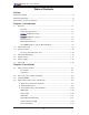
X7DAL-E+ User's Manual CPU#1 PCI-EX8 PORT #1,2 PORT PORT #4 #3 ATA 100 FBD DIMM Branch 2 Branch 1 PCIE X4 PCIE X4 FBD CHNL3 FBD DIMM PCIEX16_SLOT #6 PCI-EXP X4 PORT #0 FBD CHNL2 #2B #3A #4A #2A IDE CONN #5 #4 #3 #2 #1 #0 3.0 Gb/S ESB2 PCIX133 PORT#0 PCI 33 USB 2.
Chapter 1: Introduction 1-2 Chipset Overview Built upon the functionality and the capability of the 5000X chipset, the X7DAL-E+ motherboard provides the performance and feature set required for dual processor-based workstations with configuration options optimized for communications, presentation, storage and computation applications or for use as workstations. The 5000X chipset supports a single or two Xeon 64-bit Dual-Core or Quad-Core processor(s) with front side bus speeds of up to 1333 MHz.
X7DAL-E+ User's Manual 1-3 Special Features Recovery from AC Power Loss The feature allows the user to set the power state after a power outage. You can select Power-Off for the system power to remain off after a power loss. Select Power-On for the system power to be turned on after a power loss. Select Last State to allow the system to resume its last state before the power loss. The default setting is Last State.
Chapter 1: Introduction 1-5 ACPI Features ACPI stands for Advanced Configuration and Power Interface. The ACPI specification defines a flexible and abstract hardware interface that provides a standard way to integrate power management features throughout a PC system, including its hardware, operating system and application software. This enables the system to automatically turn on and off peripherals such as CD-ROMs, network cards, hard disk drives and printers.
X7DAL-E+ User's Manual WOL capability. In addition, an onboard LAN controller can also support WOL without any connection to the WOL header. The 3-pin WOL header is to be used with a LAN add-on card only. Note: Wake-On-LAN requires an ATX 2.01 (or above) compliant power supply. 1-6 Power Supply As with all computer products, a stable power source is necessary for proper and reliable operation. It is even more important for processors that have high CPU clock rates.
Chapter 1: Introduction The Super I/O provides functions that comply with ACPI (Advanced Configuration and Power Interface), which includes support of legacy and ACPI power management through an SMI or SCI function pin. It also features auto power management to reduce power consumption.
X7DAL-E+ User's Manual Notes 1-14
Chapter 2: Installation Chapter 2 Installation 2-1 Static-Sensitive Devices Electro-Static-Discharge (ESD) can damage electronic components. To prevent damage to your system board, it is important to handle it very carefully. The following measures are generally sufficient to protect your equipment from ESD. Precautions • Use a grounded wrist strap designed to prevent static discharge. • Touch a grounded metal object before removing the board from the antistatic bag.
X7DAL-E+ User's Manual 2-2 Processor and Heatsink Installation When handling the processor package, avoid placing ! direct pressure on the label area of the fan. Notes: 1. Always connect the power cord last and always remove it before adding, removing or changing any hardware components. Make sure that you install the processor into the CPU socket before you install the CPU heatsink. 2. Intel's boxed Xeon CPU package contains the CPU fan and heatsink assembly.
Chapter 2: Installation 2. Locate the front side of the chassis. 3. Locate the four backplate mounting holes on the chassis. 4. Align the backplate with the chassis. Make sure that the arrow on the backplate is pointing at the front side of the The Front Side of Chassis chassis. 5. Once the backplate is correctly oriented, align the four heatsink mounting holes on the backplate against their respective mounting holes on the chassis.
X7DAL-E+ User's Manual 3. Use your thumb and index finger to hold the CPU at the North Center Edge and the South Center Edge of the CPU. 4. Align CPU Pin1 (the CPU corner marked with a triangle) against the socket corner that is marked with a triangle cutout. Load Plate (w/PnP Cap attached) North Center Edge South Center Edge 5. Align the CPU key that is the semi-circle cutout below a gold dot against the socket key, the notch on the same side of the triangle cutout on the socket. 6.
Chapter 2: Installation Installing and Removing the Heatsink CEK Passive Heatsink CEK Heatsink Installation 1. Do not apply any thermal grease to the heatsink or the CPU die; the required amount Screw#1 has already been applied. Screw#2 2. Place the heatsink on top of the CPU so that the four mounting holes are aligned with those on the retention mechanism. 3. Screw in two diagonal screws (ie the #1 and the #2 screws) until just snug (-do not overtighten the screws to avoid possible damage to the CPU.
X7DAL-E+ User's Manual 2-3 Installing DIMMs Note: Check the Supermicro web site for recommended memory modules. CAUTION Exercise extreme care when installing or removing DIMM modules to prevent any possible damage. Also note that the memory is interleaved to improve performance (See step 1). DIMM Installation 1. Insert the desired number of DIMMs into the memory slots, starting with DIMM #1A.
Chapter 2: Installation Possible System Memory Allocation & Availability System Device Size Physical Memory Remaining (-Available) (4 GB Total System Memory) Firmware Hub flash memory (System BIOS) 1 MB 3.99 Local APIC 4 KB 3.99 Area Reserved for the chipset 2 MB 3.99 I/O APIC (4 Kbytes) 4 KB 3.99 PCI Enumeration Area 1 256 MB 3.76 PCI Express (256 MB) 256 MB 3.51 PCI Enumeration Area 2 (if needed) -Aligned on 256-MB boundary- 512 MB 3.01 VGA Memory 16 MB 2.85 TSEG 1 MB 2.
X7DAL-E+ User's Manual 2-4 Control Panel Connectors/IO Ports The I/O ports are color coded in conformance with the PC 99 specification. See the figure below for the colors and locations of the various I/O ports. A. Back Panel Connectors/IO Ports 6 5 13 16 2 ® SUPER X7DAL-E+ 1 10 4 3 7 8 9 12 15 11 14 Back Panel I/O Port Locations and Definitions Back Panel Connectors 1. PS/2 Keyboard (Purple) 2. PS/2 Mouse (Green) 3. Back Panel USB Port 0 4. Back Panel USB Port 1 5. Back Panel USB Port 2 6.
Chapter 2: Installation B. Front Control Panel JF1 contains header pins for various buttons and indicators that are normally located at a control panel at the front of the chassis. These connectors are designed specifically for use with Supermicro workstation chassis. See the figure below for the descriptions of the various control panel buttons and LED indicators. Refer to the following section for descriptions and pin definitions.
X7DAL-E+ User's Manual C. Front Control Panel Pin Definitions NMI Button NMI Button Pin Definitions (JF1) The non-maskable interrupt button Pin# Definition header is located at pins 19 and 20 19 Control 20 Ground of JF1. Refer to the table on the right for pin definitions. Power LED Power LED Pin Definitions (JF1) 4-Pin 8-Pin PWR PWR JPWF Alarm Reset KB/ Mouse USB 0/1/2/3 24-Pin ATX PWR PWR I2C Definition 15 +5V 16 Ground A. NMI DIMM 4A (Bank 4) B.
Chapter 2: Installation HDD LED HDD LED Pin Definitions (JF1) The HDD LED connection is located at pins 13 and 14 of JF1. Attach the hard drive LED cable here to display disk activity (for any hard drives on the Pin# Definition 13 +5V 14 HD Active system, including SAS, Serial ATA and IDE). See the table on the right for pin definitions.
X7DAL-E+ User's Manual Overheat/Fan Fail LED (OH) OH/Fan Fail LED Pin Definitions (JF1) Connect an LED to the OH/Fan Fail connection on pins 7 and 8 of JF1 to Pin# Definition 7 Vcc provide advanced warning of chassis overheating or fan failure. Refer to the 8 Ground table on the right for pin definitions.
Chapter 2: Installation Reset Button Reset Button Pin Definitions (JF1) The Reset Button connection is located at pins 3 and 4 of JF1. Attach it to the hardware reset switch on the computer case. Refer to the table on the right for Pin# Definition 3 Reset 4 Ground pin definitions. Power Button 4-Pin 8-Pin PWR PWR JPWF Alarm Reset KB/ Mouse USB 0/1/2/3 24-Pin ATX PWR PWR I2C Power Button Pin Definitions (JF1) Pin# Definition 1 Signal 2 +3V Standby LE2 A. Reset Button PWR Force-On B.
X7DAL-E+ User's Manual 2-5 ATX Power 20-pin Connector Pin Definitions Connecting Cables ATX Power Connector A 24-pin main power supply connector(JPW1) and an 8-pin CPU PWR connector (JPW3) are located on the motherboard. These power connectors meet the SSI EPS 12V specification. The 4-pin 12V PWR supply at JPW2 is required to provide adequate power to the PCI-Express slots. See the tables on the right for pin definitions. Processor Power Connector Pin# Definition 13 +3.3V 1 +3.
Chapter 2: Installation Back Panel USB (USB0/1/2/3) Universal Serial Bus (USB) Pin# Definitions Serial Bus) ports/headers on the moth- 1 +5V erboard. Four of them are Back Panel USB ports (JUSB3: USB#0/#1/#2/#3), 2 PO- 3 PO+ and the other four are Front Panel 4 Ground USB headers (JUSB1: USB#4/#5, 5 N/A There are eight USB 2.0 (Universal JUSB2: USB#6/#7). See the tables on Front Panel USB Pin Definitions (USB4/5/6/7) the right for pin definitions.
X7DAL-E+ User's Manual Fan Headers Fan Header Pin Definitions The X7DAL-E+ has six chassis/system fan headers (Fan1 to Fan6). (Note: all these fans are 4-pin fans. However, Pins 1-3 of the fan headers are backward compatible with the traditional 3-pin fans.) See the table on the right for pin definitions. (The onboard fan speeds are controlled by Thermal Management Pin# Definition 1 Ground 2 +12V 3 Tachometer 4 PWR Modulation via BIOS Hardware Monitor in the Advanced Setting.
Chapter 2: Installation PWR Supply Failure/PWR Fault Detect (JPWF) PWR Supply Fail/PWR Fault (JPWF) Pin# The system can notify you in the event of a power supply failure. This feature is available when three power supply units are installed in the chassis with one acting as a backup. If you only have one or two power supply units Definition 1 PWRF1 2 PWRF2 3 PWRF3 4 Alarm Reset installed, you should disable this (the default setting) with JPWF to prevent false alarms.
X7DAL-E+ User's Manual Wake-On-Ring Wake-On-Ring Pin Definitions (JWOR) The Wake-On-Ring header is designated JWOR. This function allows Pin# Definition your computer to "wake up" when an incoming call is received by the mo- 1 Ground 2 Wake-up dem while in suspend state. See the table on the right for pin definitions. You must have a Wake-On-Ring card and cable to use this feature.
Chapter 2: Installation GLAN 1/2 (Giga-bit Ethernet Ports) GLAN1 Two G-bit Ethernet ports are located at JLAN1 on the I/O backplane. This GLAN2 port accepts RJ45 type cables. Speaker Connector Pin Definitions Power LED/Speaker On the JD1 header, pins 1-3 are used for a power LED and pins 4-7 are for the speaker. See the table on the right for speaker pin definitions. To use an external speaker, connect a cable to pins 4-7 of this header. To use the onboard speaker, close pins 6-7 with a jumper.
X7DAL-E+ User's Manual Alarm Reset Alarm Reset Pin Definitions If three power supplies are installed Pin Setting and Alarm Reset (JP5) is enabled, the system will notify you when any of the three power modules fails. Connect Definition Pin 1 Ground Pin 2 +5V JP5 to a micro-switch to turn off the alarm that is activated when a power module fails. See the table on the right for pin definitions.
Chapter 2: Installation Power SMB (I2C) Connector PWR SMB Pin Definitions Power SMB (I2C) Connector (JPI2C) monitors the status of the power supply, fan and system temperature. See the table on the right for pin definitions. T-SGPIO Headers USB 0/1/2/3 24-Pin ATX PWR PWR I2C PWR Force-On *NC 3 Ground 4 Data 5 Load 6 Ground 7 *NC 8 *NC *Note: NC= No Connections B. T-SGPIO1 CPU1 C.
X7DAL-E+ User's Manual High Definition Audio (HDA) The X7DAL-E+ features a 7.1+2 Channel High Orange: CEN/LFE Blue: Line-In Black: Back Surround Green:Front Definition Audio (HDA) (J2) codec that provides 10DAC channels, simultaneously supporting 7.1 sound playback with 2 channels of independent stereo sound output with multiple streaming Grey: Side Pink: Mic-In Surround through the front panel stereo out to the front L&R, rear L&R, center and subwoofer speakers.
Chapter 2: Installation Front Panel Audio Control When front panel headphones are plugged in, the back panel audio output is disabled. This is done through the FP Audio header (J14). If the front panel interface card is not connected to the front panel audio header, jumpers should be installed on the pin pairs: 5-6 and 9-10 of the header (J14).
X7DAL-E+ User's Manual 2-6 Jumper Settings Explanation of Jumpers Connector Pins 3 2 1 3 2 1 To modify the operation of the motherboard, jumpers can be used to choose between optional settings. Jumpers create shorts between two pins to change the function Jumper Cap of the connector. Pin 1 is identified with a square solder pad on the printed circuit Setting board. See the motherboard layout pages Pin 1-2 short for jumper locations.
Chapter 2: Installation CMOS Clear JBT1 is used to clear CMOS. Instead of pins, this "jumper" consists of contact pads to prevent the accidental clearing of CMOS. To clear CMOS, use a metal object such as a small screwdriver to touch both pads at the same time to short the connection. Always remove the AC power cord from the system before clearing CMOS. Note: For an ATX power supply, you must completely shut down the system, remove the AC power cord and then short JBT1 to clear CMOS.
X7DAL-E+ User's Manual Audio Enable/Disable Audio Enable Jumper Settings JPAC1 enables or disables the Audio Controller on the motherboard. See the table on the right for jumper settings. The default setting is enabled. I2C Bus to PCI Slots Pin# Definition 1-2 Enabled (*default) 2-3 Disabled I2C to PCI-Slots Jumper Settings JI2C1/JI2C2 Jumpers allow you to connect the System Management Bus (I2C) to PCI Jumper Setting Definition slots.
Chapter 2: Installation Power Force On Enable/Disable Power Force On Enable/Disable Jumper Settings (JPF) Jumper JPF allows you to enable the function of Power Force-On. If enabled, the power will Jumper Setting always stay on automatically.
X7DAL-E+ User's Manual Activity LED Link (Green) LED There are two GLAN ports on the moth- Activity LED Link erboard. Each Gigabit Ethernet LAN port (Green) LED 2-7 Onboard Indicators GLAN LEDs (Rear View: When viewing from the back of the system) has two LEDs. The Green LED indicates activity. The other LED may be green, GLAN Activity Indicator amber or off to indicate the speed of the connection. See the tables at right for Color Status Definition more information.
Chapter 2: Installation CPU VRM Overheat LED Indicators (LE2/LE3) CPU VRM Overheat LEDs (LE2, LE3) LED Settings There are two CPU VRM Overheat LEDs LED Color Definition (LE2, LE3) on the motherboard. LE2 is for Off CPU1VRM, and LE3 is for CPU2 VRM. When the temperature of a CPU VRM is CPU VRM Temperature: Normal Yellow CPU VRM over 900C, CPU slows down normal, the CPU VRM Overheat LED is off.
X7DAL-E+ User's Manual Status LED (D31) Status LED Indicator LED Settings A Status LED Indicator is located at D31 LED Color on the motherboard. This LED displays Green Power On, system: normal Red PWR on, PWR problem(s) occur(s) or JPW3 not properly installed Amber System off with PWR cable connected different colors to show the status of the system. When this amber LED is on, the power cable is still connected.
Chapter 2: Installation 2-8 Parallel, Floppy Drive, PCI-U Universal and Hard Disk Drive Connections Note the following when connecting the floppy and hard disk drive cables: • The floppy disk drive cable has 34 twisted wires. • A red mark on a wire typically designates the location of pin 1. Parallel (Printer) Header Parallel (Printer) Port Connector Pin Definitions The parallel (printer) header is located Pin# Definition at J21.
X7DAL-E+ User's Manual Floppy Connector Floppy Drive Connector Pin Definitions (Floppy) The floppy connector is located at Pin# Definition J22. See the table below for pin 1 Ground 2 FDHDIN definitions.
Chapter 2: Installation IDE Connector IDE Drive Connectors Pin Definitions There is one IDE Connector on the Pin# Definition motherboard.
X7DAL-E+ User's Manual Notes 2-34
Chapter 3: Troubleshooting Chapter 3 Troubleshooting 3-1 Troubleshooting Procedures Use the following procedures to troubleshoot your system. If you have followed all of the procedures below and still need assistance, refer to the ‘Technical Support Procedures’ and/or ‘Returning Merchandise for Service’ section(s) in this chapter. Note: Always disconnect the power cord before adding, changing or installing any hardware components. Before Power On 1.
X7DAL-E+ User's Manual Section 1-6 for details on recommended power supplies. 2. The battery on your motherboard may be old. Check to verify that it still supplies ~3VDC. If it does not, replace it with a new one. 3. If the above steps do not fix the Setup Configuration problem, contact your vendor for repairs. NOTE If you are a system integrator, VAR or OEM, a POST diagnostics card is recommended. For I/O port 80h codes, refer to App. B. Memory Errors 1.
Chapter 3: Troubleshooting • BIOS release date/version (this can be seen on the initial display when your system first boots up) •System configuration An example of a Technical Support form is on our web site at (http://www.supermicro.com/support/contact.cfm). 4. Distributors: For immediate assistance, please have your account number ready when placing a call to our technical support department. We can be reached by e-mail at support@supermicro.com or by fax at: (408) 503-8000, option 2.
X7DAL-E+ User's Manual 3-4 Returning Merchandise for Service A receipt or copy of your invoice marked with the date of purchase is required before any warranty service will be rendered. You can obtain service by calling your vendor for a Returned Merchandise Authorization (RMA) number. When returning to the manufacturer, the RMA number should be prominently displayed on the outside of the shipping carton, and mailed prepaid or hand-carried.
Chapter 4: BIOS Chapter 4 BIOS 4-1 Introduction This chapter describes the Phoenix BIOS™ Setup utility for the X7DAL-E+. The Phoenix ROM BIOS is stored in a flash chip and can be easily upgraded using a floppy disk-based program. Note: Due to periodic changes to the BIOS, some settings may have been added or deleted and might not yet be recorded in this manual. Please refer to the Manual Download area of the Supermicro web site
X7DAL-E+ User's Manual 4-2 Running Setup *Default settings are in bold text unless otherwise noted. The BIOS setup options described in this section are selected by choosing the appropriate text from the main BIOS Setup screen. All displayed text is described in this section although the screen display is often all you need to understand how to set the options (see the next page). When you first power on the computer, Phoenix BIO is immediately activated.
Chapter 4: BIOS Main BIOS Setup Menu Main Setup Features System Time To set the system date and time, key in the correct information in the appropriate fields. Then press the key to save the data. System Date Using the arrow keys, highlight the month, day and year fields, and enter the correct data. Press the key to save the data. BIOS Date This field displays the date when this version of BIOS was built.
X7DAL-E+ User's Manual XIDE Channel 0 Master/Slave, SATA Port0, SATA Port1, SATA Port2 and SATA Port3 These settings allow the user to set the parameters of the slots indicated above. Press to activate the following submenu screen for detailed options of these items. Set the correct configurations accordingly. The items included in the submenu are: Type This option allows the user to select the type of IDE hard drive.
Chapter 4: BIOS CHS Format The following items will be displayed by the BIOS: TYPE: This item displays the type of IDE or SATA Device. Cylinders: This item indicates the status of Cylinders. Headers: This item indicates the number of headers. Sectors: This item displays the number of sectors. Maximum Capacity: This item displays the maximum storage capacity of the system.
X7DAL-E+ User's Manual Serial ATA Select Enabled to enable Serial ATA. The options are Disabled and Enabled. Native Mode Operation Use this feature to select native mode settings for ATA. The options are: Serial ATA and Auto. SATA Controller Mode Select Compatible to allow the SATA and PATA drives to be automatically-detected and be placed in the Legacy Mode by the BIOS. Select Enhanced to allow the SATA and PATA drives to be to be automatically-detected and placed in the Native IDE Mode.
Chapter 4: BIOS 4-4 Advanced Setup Choose Advanced from the Phoenix BIOS Setup Utility main menu with the arrow keys. You should see the following display. The items with a triangle beside them have sub menus that can be accessed by highlighting the item and pressing . XBoot Features Access the submenu to make changes to the following settings. QuickBoot Mode If enabled, this feature will speed up the POST (Power On Self Test) routine by skipping certain tests after the computer is turned on.
X7DAL-E+ User's Manual ACPI Sleep Mode Use the feature to configure the ACPI (Advanced Configuration and Power Interface) power management settings for your system when the system is in the sleep mode. The options are S1, S3 and S1 & S3. Power Button Behavior If set to Instant-Off, the system will power off immediately as soon as the user presses the power button. If set to 4-sec., the system will power off when the user presses the power button for 4 seconds or longer.
Chapter 4: BIOS Cache Video BIOS Area This setting allows you to designate a reserve area in the system memory to be used as a Video BIOS buffer to allow the BIOS to write (cache) data into this reserved memory area. Select Write Protect to enable the function and this area will be reserved for Video BIOS ROM access only. Select Uncached to disable this function and make this area available for other devices.
X7DAL-E+ User's Manual Discrete MTRR Allocation If enabled, MTRRs (-Memory Type Range Registers) are configured as distinct, separate units and cannot be overlapped. If enabled, the user can achieve better graphic effects when using a Linux graphic driver that requires the write-combining configuration with 4GB or more memory. The options are Enabled and Disabled. XPCI Configuration Access the submenu to make changes to the following settings for PCI devices.
Chapter 4: BIOS Frequency for PCI-X#2-#3 This option allows the user to change the bus frequency for the devices installed in the slot indicated. The options are Auto, PCI 33 MHz, PCI 66 MHz, PCI-X 66 MHz, PCI-X 100 MHz, and PCI-X 133 MHz.
X7DAL-E+ User's Manual 4GB PCI Hole Granularity This feature allows you to select the granularity of PCI hole for PCI slots. If MTRRs are not enough, this option may be used to reduce MTRR occupation. The options are: 256 MB, 512 MB, 1GB and 2GB. Memory Branch Mode This option determines how the memory branch operates. System address space can either be interleaved between two channels or Sequential from one channel to another. Single Channel 0 allows a single DIMM population during system manufacturing.
Chapter 4: BIOS Global Activation Throttle Select Enabled to enable open-loop global thermal throttling on a fully buffered (FBD) memory module to make it active whenever the number of activation exceeds a predefined number. The options are Enabled and Disabled. Snoop Filter Select Enabled to eliminate snoop traffic to the graphics port to greatly improve system performance when running graphics-intensive applications. The options are Enabled and Disabled.
X7DAL-E+ User's Manual XAdvanced Processor Options Access the submenu to make changes to the following settings. CPU Speed This is a display that indicates the speed of the installed processor. Frequency Ratio (Available when supported by the CPU.) The feature allows the user to set the internal frequency multiplier for the CPU. The options are: Default, x12, x13, x14, x15, x16, x17 and x18. Hyperthreading (Available when supported by the CPU.
Chapter 4: BIOS Adjacent Cache Line Prefetch (Available when supported by the CPU.) The CPU fetches the cache line for 64 bytes if this option is set to Disabled. The CPU fetches both cache lines for 128 bytes as comprised if Enabled. The options are Disabled and Enabled. Hardware Prefetcher (Available when supported by the CPU.
X7DAL-E+ User's Manual Base I/O Address This setting allows you to select the base I/O address for Serial Port A. The options are 3F8, 2F8, 3E8, and 2E8. Interrupt This setting allows you to select the IRQ (interrupt request) for Serial Port A. The options are IRQ3 and IRQ4. Serial Port B This setting allows you to decide how Serial Port B is controlled. The options are Enabled (user defined), Disabled, Auto (BIOS controlled) and OS Controlled.
Chapter 4: BIOS DMA Channel This item allows you to select the DMA channel for the Parallel Port. The options are DMA1 and DMA3. Floppy Disk Controller This setting allows you to decide how the floppy disk drive is controlled. The options are Enabled (user defined), Disabled, and Auto (BIOS and OS controlled). Base I/O Address This setting allows you to select the base I/O address for the floppy disk drive. The options are Primary and Secondary.
X7DAL-E+ User's Manual XConsole Redirection Access the submenu to make changes to the following settings. COM Port Address This item allows you to specify which COM port to direct the remote console to: Onboard COM A or Onboard COM B. This setting can also be Disabled. BAUD Rate This item allows you to set the BAUD rate for Console Redirection. The options are 300, 1200, 2400, 9600, 19.2K, 38.4K, 57.6K, and 115.2K. Console Type This item allows you to choose the type of Console Redirection.
Chapter 4: BIOS XHardware Monitor Logic Note: The Phoenix BIOS will automatically detect the type of CPU(s) and hardware monitoring chip used on the motherboard and will display the Hardware Monitoring Screen accordingly. Your Hardware Monitoring Screen may look like the one shown on this page, on P. 4-20, or on P. 4-21. It depends on the type of CPU(s) and HW Monitoring chip you are using.
X7DAL-E+ User's Manual XHardware Monitor Logic (See the Note on Page 4-19.) CPU Temperature Threshold This option displays the CPU temperature threshold that will activate the alarm system when the CPU temperature reaches this pre-set threshold. The options are 75oC, 80oC, 85oC and 90oC. (See the note below.
Chapter 4: BIOS XHardware Monitor Logic (See the Note on Page 4-19.) CPU Temperature Threshold This option displays the CPU temperature threshold that will activate the alarm system when the CPU temperature reaches this pre-set threshold. The options are 75oC, 80oC, 85oC and 90oC. (See the note below.
X7DAL-E+ User's Manual 4-5 Security Choose Security from the Phoenix BIOS Setup Utility main menu with the arrow keys. You should see the following display. Security setting options are displayed by highlighting the setting using the arrow keys and pressing . All Security BIOS settings are described in this section. Supervisor Password Is: This feature indicates if a supervisor password has been entered to the system.
Chapter 4: BIOS Password on Boot This setting allows you to determine if a password is required for a user to enter the system at bootup. The options are Enabled (password required) and Disabled (password not required). 4-6 Boot Choose Boot from the Phoenix BIOS Setup Utility main menu with the arrow keys. You should see the following display. See details on how to change the order and specs of boot devices in the Item Specific Help window. All Boot BIOS settings are described in this section.
X7DAL-E+ User's Manual 4-7 Exit Choose Exit from the Phoenix BIOS Setup Utility main menu with the arrow keys. You should see the following display. All Exit BIOS settings are described in this section. Exit Saving Changes Highlight this item and hit to save any changes you have made and to exit the BIOS Setup utility. Exit Discarding Changes Highlight this item and hit to exit the BIOS Setup utility without saving any changes you may have made.
Appendix A: BIOS Error Beep Codes Appendix A BIOS Error Beep Codes During the POST (Power-On Self-Test) routines, which are performed each time the system is powered on, errors may occur. Non-fatal errors usually allow the system to continue with bootup. The error messages normally appear on the screen. Fatal errors will not allow the system to continue with bootup in most cases. If a fatal error occurs, you should consult with your system manufacturer for possible repairs.
X7DAL-E+ User’s Manual Notes A-2
Appendix B: Installing the Windows OS Appendix B Installing the Windows OS After all hardware components have been installed, you must first configure Intel South Bridge RAID Settings before you install the Windows OS and other software drivers. To configure RAID settings, please refer to RAID Configuration User Guides posted on our website at www.supermicro.com/support/manuals. B-1 Installing the Windows XP/2000/2003 OS for Systems with RAID Functions 1.
X7DAL-E+ User's Manual B-2 Installing the Windows XP/2000/2003 OS for Systems without RAID Functions 1. Insert Microsoft's Windows XP/2000/2003 Setup CD in the CD Driver, and the system will start booting up from CD. 2. Continue with the OS installation. The Windows OS Setup screen will display. 3. From the Windows XP/2000/2003 Setup screen, press the key. The XP/2000/2003 Setup will automatically load all device files and then continue with the Windows XP/2000/2003 installation. 4.
Appendix C: Installing Other Software Programs and Drivers Appendix C Installing Other Software Programs and Drivers C-1 Installing Drivers other than the Adaptec Embedded Serial ATA RAID Controller Driver After you have installed the Windows Operating System, a screen as shown below will appear. You are ready to install software programs and drivers that have not yet been installed. To install these software programs and drivers, click the icons to the right of these items.
X7DAL-E+ User's Manual C-2 Configuring Supero Doctor III The Supero Doctor III program is a web-based management tool that supports remote management capability. It includes Remote and Local Management tools. The local management is called the SD III Client. The Supero Doctor III program included on the CDROM that came with your motherboard allows you to monitor the environment and operations of your system.
Appendix C: Installing Other Software Programs and Drivers Supero Doctor III Interface Display Screen-II (Remote Control) Note: The SD III Software program can be downloaded from our Web site at: ftp://ftp. supermicro.com/utility/Supero_Doctor_III/. You can also download the SDIII User's Guide at: http://www.supermicro.com/PRODUCT/Manuals/SDIII/UserGuide.pdf. For Linux, we will still recommend that you use Supero Doctor II.
X7DAL-E+ User's Manual Notes C-4
(Disclaimer continued) The products sold by Supermicro are not intended for and will not be used in life support systems, medical equipment, nuclear facilities or systems, aircraft, aircraft devices, aircraft/emergency communication devices or other critical systems whose failure to perform be reasonably expected to result in significant injury or loss of life or catastrophic property damage.