SUPER X7DB3 USER’S MANUAL Revision 1.
The information in this User’s Manual has been carefully reviewed and is believed to be accurate. The vendor assumes no responsibility for any inaccuracies that may be contained in this document, makes no commitment to update or to keep current the information in this manual, or to notify any person or organization of the updates. Please Note: For the most up-to-date version of this manual, please see our web site at www.supermicro.com. Super Micro Computer, Inc.
Preface Preface About This Manual This manual is written for system integrators, PC technicians and knowledgeable PC users. It provides information for the installation and use of X7DB3 motherboard. The X7DB3 supports dual Intel 64-bit quad the core/dual core processors at a front side bus speed of 1.333 GHz/1.066 GHz/677 MHz.
X7DB3 User's Manual Table of Contents Preface About This Manual ...................................................................................................... iii Manual Organization ................................................................................................... iii Conventions Used in the Manual .................................................................................. iii Chapter 1: Introduction 1-1 Overview ...........................................................
Table of Contents Power Button .......................................................................................... 2-13 2-5 Connecting Cables ....................................................................................... 2-14 ATX Power Connector .......................................................................... 2-14 Processor Power Connector ................................................................. 2-14 Universal Serial Bus (USB0/1) ..........................................
X7DB3 User's Manual SIMLP IPMI Slot ...................................................................................... 2-32 IDE Connectors ....................................................................................... 2-33 Chapter 3: Troubleshooting 3-1 Troubleshooting Procedures ........................................................................... 3-1 Before Power On....................................................................................... 3-1 No Power.....................
Chapter 1: Introduction Chapter 1 Introduction 1-1 Overview Checklist Congratulations on purchasing your computer motherboard from an acknowledged leader in the industry. Supermicro boards are designed with the utmost attention to detail to provide you with the highest standards in quality and performance. Check that the following items have all been included with your motherboard. If anything listed here is damaged or missing, contact your retailer.
X7DB3 User's Manual Contacting Supermicro Headquarters Address: Super Micro Computer, Inc. 980 Rock Ave. San Jose, CA 95131 U.S.A. Tel: +1 (408) 503-8000 Fax: +1 (408) 503-8008 Email: marketing@supermicro.com (General Information) support@supermicro.com (Technical Support) Web Site: www.supermicro.com Europe Address: Super Micro Computer, B.V. Het Sterrenbeeld 28, 5215 ML 's-Hertogenbosch, The Netherlands Tel: +31 (0) 73-6400390 Fax: +31 (0) 73-6416525 Email: sales@supermicro.
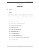
Chapter 1: Introduction X7DB3 Image Note: The drawings and pictures shown in this manual were based on the latest PCB Revision available at the time of publishing of the manual. The motherboard you’ve received may or may not look exactly the same as the graphics shown in the manual.
X7DB3 User's Manual X7DB3 Motherboard Layout (not drawn to scale) DIMM 4B (B a nk 4) J 9B 1 DIMM 4A (B a nk 4) J 8B 3 DIMM 3B (B a nk 3) J 8B 2 DIMM 3A (B a nk 3) J 8B 1 DIMM 2B (B a nk 2) J F1 PW LED SPK Fan2 F P C ontrol Fan1 J P1 J D1 VGAJ 15 J 9B 2 Xeon Dual Core C P U1 J 7B 3 DIMM 2A (B a nk 2) J 7B 2 DIMM 1B (B a nk 1) J 7B 1 DIMM 1A (B a nk 1) LE1 GLAN1 J LAN1 Xeon Dual Core Fan3 GLAN2 J LAN2 C P U2 ® Fan8 North B ridge S lot6 S lot5 x8 J 5 S E PCJ 11
Chapter 1: Introduction Quick Reference ( X7DB3) Jumper 27, J28 J3P Description I2C Bus to PCI-X/PCI-E Slots 3rd PWR Failure Detect Open (Disabled) JBT1 CMOS Clear See Chapter 2 JCF1 JPG1 Compact Card Master/Slave Select VGA Enable On (Master) Pins 1-2 (Enabled) JPL1/ JPL2 GLAN1/GLAN2 Enable Pins 1-2 (Enabled) SAS Controller Enable Pins 1-2 (Enabled) JPS1 JWD Watch Dog Default Setting Open (Disabled) Pins 1-2 (Reset) Connector Description ATX PWR (JPW1) Primary 24-Pin ATX PWR Connector
X7DB3 User's Manual Motherboard Features CPU • Dual Intel® 64-bit Xeon LGA 771 quad core/dual core processors at a front side bus speed of 1.333 GHz/1.066 GHz/677 MHz with a system clock speed of 333/267/166 MHz Memory • Eight 240-pin DIMM sockets with support up to 32 GB DDR2 Fully Buffered (FBD) ECC 667/533 Memory (*See Section 2-3 in Chapter 2 for DIMM Slot Population.
Chapter 1: Introduction • Intel Virtualization Technology support • PECI (Platform Enhancement Configuration Interface) ready ACPI Features • Slow blinking LED for suspend state indicator • Main switch override mechanism • ACPI Power Management Onboard I/O • Adaptec AIC 9410 SAS Controller supports eight SAS ports (RAID 0, 1,10) • Six SATA 3.
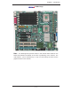
X7DB3 User's Manual PORT #4 AT A 100 PORT #3 9410W PCI - X133 PCI - X133 A B PCI - E XPX8 PXH #4A #4B I DE CONN E BUS CONN #5 #4 #3 #2 #1 #0 PORT #1, 2 E S B2 S AT A AIC #3B #2B PORT #0 PCI E X4 PCI E X8 PORT #0 F BD DIMM F BD CHNL 3 PORT #2, 3 F BD F BD CHNL 2 F BD DIMM # 2 A #1A #1B F BD CHNL 1 PORT #6, 7 PCI -E XP X8 S E PC PCI - E XP X8 S L OT F BD CHNL 0 5000P MCH PORT #4, 5 E XP. BUS J 14 #3 3.
Chapter 1: Introduction 1-2 Chipset Overview Built upon the functionality and the capability of the 5000P chipset, the X7DB3 motherboard provides the performance and feature set required for dual processor-based servers with configuration options optimized for communications, presentation, storage, computation and database applications. The 5000P chipset supports single or dual 64-bit quad core/dual core processor(s) with front side bus speeds of up to 1.333 GHz/1.066 GHz/677 MHz.
X7DB3 User's Manual 1-3 Special Features Recovery from AC Power Loss BIOS provides a setting for you to determine how the system will respond when AC power is lost and then restored to the system. You can choose for the system to remain powered off (in which case you must hit the power switch to turn it back on), or for it to automatically return to power-on state, or you can also choose for it to automatically return to the last state prior to power loss.
Chapter 1: Introduction can be alerted of the potential problem. You can also configure Supero Doctor to provide you with warnings when the system temperature goes beyond a pre-defined range. 1-5 ACPI Features ACPI stands for Advanced Configuration and Power Interface. The ACPI specification defines a flexible and abstract hardware interface that provides a standard way to integrate power management features throughout a PC system, including its hardware, operating system and application software.
X7DB3 User's Manual Wake-On-LAN (WOL) Wake-On-LAN is defined as the ability of a management application to remotely power up a computer that is powered off. Remote PC setup, up-dates and asset tracking can occur after hours and on weekends so that daily LAN traffic is kept to a minimum and users are not interrupted. The motherboard has a 3-pin header (WOL) to connect to the 3-pin header on a Network Interface Card (NIC) that has WOL capability.
Chapter 1: Introduction ports (UARTs. Each UART includes a 16-byte send/receive FIFO, a programmable baud rate generator, complete modem control capability and a processor interrupt system. Both UARTs provide legacy speed with baud rate of up to 115.2 Kbps as well as an advanced speed with baud rates of 250 K, 500 K, or 1 Mb/s, which support higher speed modems.
X7DB3 User's Manual Notes 1-14
Chapter 2: Installation Chapter 2 Installation 2-1 Static-Sensitive Devices Electro-Static-Discharge (ESD) can damage electronic components. To prevent damage to your system board, it is important to handle it very carefully. The following measures are generally sufficient to protect your equipment from ESD. Precautions • Use a grounded wrist strap designed to prevent static discharge. • Touch a grounded metal object before removing the board from the antistatic bag.
X7DB3 User's Manual 2-2 Processor and Heatsink Fan Installation When handling the processor package, avoid placing ! direct pressure on the label area of the fan. Notes: • Always connect the power cord last and always remove it before adding, removing or changing any hardware components. Make sure that you install the processor into the CPU socket before you install the CPU heatsink. • Intel's boxed Xeon CPU package contains the CPU fan and heatsink assembly.
Chapter 2: Installation 3. Use your thumb and your index North Center Edge finger to hold the CPU at the North Center Edge and the South Center Edge of the CPU. 4. Align CPU Pin1 (the CPU corner marked with a triangle) against the socket corner that is marked with a South Center Edge triangle cutout. 5. Align the CPU key that is the Socket Key semi-circle cutout below a gold dot (Socket Notch) gold dot against the socket key, the notch on the same side of the triangle cutout on the socket. 6.
X7DB3 User's Manual Heatsink Installation CEK Heatsink Installation CEK Passive Heatsink 1. Do not apply any thermal grease to the heatsink or the CPU die-the required amount has already been applied. 2. Place the heatsink on top of the CPU so that the four mounting holes are aligned with those on the retention mechanism. Screw#1 3. Screw in two diagonal screws (ie the #1 and the #2 screws) until just snug (-do not fully tighten the screws to avoid possible damage to the CPU.
Chapter 2: Installation 1. Unscrew and remove the heatsink screws from the motherboard in the sequence as show in the picture on the right. 2. Hold the heatsink as shown in the picture on the right and gently wriggle the heatsink to loosen it from the CPU. (Do not use excessive force when wriggling the heatsink!!) 3. Once the CPU is loosened, remove the heatsink from the CPU socket. 4. Clean the surface of the CPU and the heatsink to get rid of the old thermal grease.
X7DB3 User's Manual 2-3 Installing DIMMs Note: Check the Super Micro web site for recommended memory modules. CAUTION Exercise extreme care when installing or removing DIMM modules to prevent any possible damage. Also note that the memory is interleaved to improve performance (see step 1). DIMM Installation (See Figure 2-2) 1. Insert the desired number of DIMMs into the memory slots, starting with DIMM #1A.
Chapter 2: Installation Possible System Memory Allocation & Availability System Device Size Physical Memory Remaining (-Available) (4 GB Total System Memory) Firmware Hub flash memory (System BIOS) 1 MB 3.99 Local APIC 4 KB 3.99 Area Reserved for the chipset 2 MB 3.99 I/O APIC (4 Kbytes) 4 KB 3.99 PCI Enumeration Area 1 256 MB 3.76 PCI Express (256 MB) 256 MB 3.51 PCI Enumeration Area 2 (if needed) -Aligned on 256-MB boundary- 512 MB 3.01 VGA Memory 16 MB 2.85 TSEG 1 MB 2.
X7DB3 User's Manual 2-4 Control Panel Connectors/IO Ports The I/O ports are color coded in conformance with the PC 99 specification. See Figure 2-3 below for the colors and locations of the various I/O ports. J L A N1 A. Back Panel Connectors/IO Ports S UP E R 2 4 1 3 7 ® X 7DB 3 5 6 Back Panel I/O Port Locations and Definitions Back Panel Connectors 1. Keyboard (Purple) 2. PS/2 Mouse (Green) 3. Back Panel USB Port 0 4. Back Panel USB Port 1 5. COM Port 1 (Turquoise) 6. VGA Port (Blue) 7.
Chapter 2: Installation B. Front Control Panel JF1 contains header pins for various buttons and indicators that are normally located on a control panel at the front of the chassis. These connectors are designed specifically for use with Super Micro server chassis. See Figure 2-4 for the descriptions of the various control panel buttons and LED indicators. Refer to the following section for descriptions and pin definitions.
X7DB3 User's Manual C. Front Control Panel Pin Definitions NMI Button NMI Button Pin Definitions (JF1) The non-maskable interrupt button Pin# Definition header is located on pins 19 and 20 19 Control 20 Ground of JF1. Refer to the table on the right for pin definitions. Power LED The Power LED connection is located on pins 15 and 16 of JF1. Refer to the table on the right for pin definitions. Power LED Pin Definitions (JF1) Pin# Definition 15 +5V 16 Ground A. NMI B.
Chapter 2: Installation HDD LED HDD LED Pin Definitions (JF1) The HDD LED connection is located on pins 13 and 14 of JF1. Attach the hard drive LED cable here to display disk activity (for any hard drives on Pin# Definition 13 +5V 14 HD Active the system, including SAS, Serial ATA and IDE). See the table on the right for pin definitions.
X7DB3 User's Manual Overheat/Fan Fail LED (OH) OH/Fan Fail LED Pin Definitions (JF1) Connect an LED to the OH/Fan Fail connection on pins 7 and 8 of JF1 to provide advanced warnings of chassis overheating or fan failure. Refer to the Pin# Definition 7 Vcc 8 Ground OH/Fan Fail Indicator Status table on the right for pin definitions.
Chapter 2: Installation Reset Button The Reset Button connection is located Reset Button Pin Definitions (JF1) on pins 3 and 4 of JF1. Attach it to the hardware reset switch on the computer case. Refer to the table on the right for Pin# Definition 3 Reset pin definitions. 4 Ground Power Button Power Button Pin Definitions (JF1) The Power Button connection is located on pins 1 and 2 of JF1. Momentarily contacting both pins will power on/off the system.
X7DB3 User's Manual 2-5 Connecting Cables ATX Power 24-pin Connector Pin Definitions Pin# Definition 13 +3.3V 1 +3.3V There are a 24-pin main power sup- 14 -12V 2 +3.3V ply connector(JPW1) and an 8-pin 15 COM 3 COM CPU PWR connector (JPW3) on the motherboard. These power connec- 16 PS_ON 4 +5V 17 COM 5 COM tors meet the SSI EPS 12V specifica- 18 COM 6 +5V tion.
Chapter 2: Installation Universal Serial Bus (USB) Back Panel USB (USB0/1) There are five USB 2.0 (Universal Serial Bus) ports/headers on the motherboard. Two of them are Back Panel USB ports (USB#0/1:JUSB1), and the other three are Front Panel USB headers (USB#2/3:JUSB2, USB#4: JUSB3). See the tables on the right Front Panel USB (USB2/3) Pin# Definitions Pin# Definition 1 +5V 1 +5V 2 PO- 2 Data- 3 PO+ 3 Data+ 4 Ground 4 Ground 5 N/A 5 NA for pin definitions.
X7DB3 User's Manual Fan Headers Fan Header Pin Definitions (Fan1-8) The X7DB3 has six chassis/system fan headers (Fan1 to Fan6) and two CPU Fans (Fan7 and Fan8). (*Note: Fans#1-4 are 3-pin fans. Fans#5-8 are 4-pin fans. However, Pins 1-3 of the fan headers are backward compatible with the traditional 3-pin fans.) See the table on Pin# Definition 1 Ground 2 +12V 3 Tachometer 4 PWR Modulation the right for pin definitions.
Chapter 2: Installation ATX PS/2 Keyboard and PS/2 Mouse Ports PS/2 Keyboard and Mouse Port Pin Definitions The ATX PS/2 keyboard and the PS/2 Pin# Definition mouse are located at JKM1. See the 1 Data table on the right for pin definitions. (The mouse port is above the key- 2 NC 3 Ground board port. See the table on the right 4 VCC for pin definitions.
X7DB3 User's Manual Wake-On-Ring Wake-On-Ring Pin Definitions (JWOR) The Wake-On-Ring header is designated JWOR. This function allows your computer to receive and be awakened by an incoming call to the Pin# Definition 1 Ground 2 Wake-up modem when the system is in the suspend state. See the table on the right for pin definitions. You must have a Wake-On-Ring card and cable to use this feature.
Chapter 2: Installation GLAN 1/2 (Giga-bit Ethernet Ports) Two G-bit Ethernet ports are designated JLAN1 and JLAN2 on the IO GLAN1 GLAN2 backplane. This port accepts RJ45 type cables. Power LED/Speaker On the JD1 header, pins 1-3 are for a power LED and pins 4-7 are for the speaker. See the table on the right for speaker pin definitions. Note: The speaker connector pins are for use with an external speaker. If you wish to use the onboard speaker, you should close pins 6-7 with a jumper.
X7DB3 User's Manual Power Fault (PWR Supply Failure) PWR Supply Fail LED Pin Definitions Connect a cable from your power supply to the Power Fail (PSF) header (JP3) to provide warnings of power supply failure. This warning signal is passed through the PWR_LED pin to indicate of a power failure on the chassis. See the table on the right for pin definitions.
Chapter 2: Installation Overheat LED/Fan Fail (JOH1) Overheat LED Pin Definitions The JOH1 header is used to connect an LED to provide warnings of chassis overheating. This LED will blink to indicate a fan failure. Refer to the Pin# Definition 1 5vDC 2 OH Active OH/Fan Fail LED table on right for pin definitions. State Message Solid Overheat Blinking Fan Fail SMB SMB Header Pin Definitions A System Management Bus header is located at J18.
X7DB3 User's Manual Power SMB (I2 C) Connector PWR SMB Pin Definitions Power SMB (I2 C) Connector (J17) monitors the status of PWR supply, fan and system temperature. See the table on the right for pin definitions. Pin# Definition 1 Clock 2 Data 3 PWR Fail 4 Ground 5 +3.3V VGA Connector A VGA connector (JG1) is located next to COM1 port on the IO backplane. Refer to the board layout below for the location.
Chapter 2: Installation Compact Flash Card PWR Connector A Compact Flash Card PWR Connector Compact Flash Card Power Jumper Definition Connector is located at JWF1. For the On Compact Flash Card or the Compact Flash Jumper (JCF1) to work properly, Compact Flash Power On Off Compact Flash Power Off you will need to connect the Compact Flash Card power cable to JWF1 first. Refer to the board layout below for the location.
X7DB3 User's Manual 2-6 Jumper Settings Explanation of Jumpers Connector Pins To modify the operation of the mother- 3 2 1 3 2 1 board, jumpers can be used to choose between optional settings. Jumpers create shorts between two pins to Jumper Cap change the function of the connector. Pin 1 is identified with a square solder Setting pad on the printed circuit board. See the motherboard layout pages for jumper locations.
Chapter 2: Installation CMOS Clear JBT1 is used to clear CMOS. Instead of pins, this "jumper" consists of contact pads to prevent the accidental clearing of CMOS. To clear CMOS, use a metal object such as a small screwdriver to touch both pads at the same time to short the connection. Always remove the AC power cord from the system before clearing CMOS. Note: For an ATX power supply, you must completely shut down the system, remove the AC power cord and then short JBT1 to clear CMOS.
X7DB3 User's Manual SAS Controller Enable/Disable SAS Controller Enable Jumper Settings JPS1 enables or disables the AIC Jumper Setting 9410W Adaptec SAS Controller on the motherboard. See the table on the right for jumper settings. The default setting Definition Pins 1-2 Enabled (*default) Pins 2-3 Disabled is enabled. VGA Enable/Disable VGA Enable/Disable Jumper Settings (JPG1) JPG1 allows you to enable or disable the VGA port. The default position is on pins 1 and 2 to enable VGA.
Chapter 2: Installation 3rd PWR Supply PWR Fault Detect J3P) 3rd PWR Supply PWR Fault Jumper Settings Jumper Setting The system can notify you in the event of a power supply failure. This feature is available when three power supply units are installed in the chassis with one act- Definition Closed Enabled Open Disabled (*Default) ing as a backup. If you only have one or two power supply units installed, you should disable this (the default setting) with J3P to prevent false alarms.
X7DB3 User's Manual Compact Flash Master/Slave Select Compact Flash Card Master/ Slave Select Jumper Definition A Compact Flash Master (Primary)/Slave (Secondary) Select Jumper is located at JCF1. Close this jumper to enable Compact Flash Card. For the Compact Open Slave (Secondary) Closed Master (Primary) Flash Card or the Compact Flash Jumper (JCF1) to work properly, you will need to connect the Compact Flash Card power cable to JWF1 first. Refer to the board layout below for the location.
Chapter 2: Installation 2-7 Onboard Indicators GLAN LEDs L i n k L E D ( o ff , Activity LED green, amber) (yellow) There are two GLAN ports on the moth- Rear View (When Viewing from the back of the systgem) erboard. Each Gigabit Ethernet LAN port has two LEDs. The yellow LED indicates activity, while the power LED may be GLAN Activity Indicator (Yellow) green, orange or off to indicate the speed of the connection.
X7DB3 User's Manual Backpanel SAS Activity LED Header Backpanel SAS_ACT_Output Pin Definitions Pin# Definition Backpanel SAS Activity LED Header Pin# Definition 1 SAS0:Act 6 SAS4:Act 2 SAS1:Act 7 SAS5:Act 3 SAS2:Act 8 SAS6:Act mon LED will be activated when any of 4 SAS3:Act 9 SAS7:Act SAS0 to SAS7 LEDs is activated.) 5 *SAS Common 10 NC (JSLED1), located next to IDE1, indicates SAS Activity status. See the table on the right for pin definitions.
Chapter 2: Installation 2-8 Parallel Port, Floppy Drive, Hard Disk Drive and SIMLP IPMI Connections Note the following when connecting the floppy and hard disk drive cables: • The floppy disk drive cable has seven twisted wires. • A red mark on a wire typically designates the location of pin 1. • A single floppy disk drive ribbon cable has 34 wires and two connectors to provide for two floppy disk drives.
X7DB3 User's Manual Floppy Connector Floppy Drive Connector Pin Definitions (Floppy) The floppy connector is located at Pin# Definition J21. See the table below for pin 1 Ground 2 FDHDIN definitions.
Chapter 2: Installation IDE Connectors IDE Drive Connectors Pin Definitions There are two IDE Connectors (JIDE1: Pin# Definition Blue, JIDE2: White) on the moth- 1 Reset IDE 2 Ground 3 Host Data 7 4 Host Data 8 5 Host Data 6 6 Host Data 9 IDE Drive. The white IDE connector 7 Host Data 5 8 Host Data 10 (JIDE2) is designated the Second- 9 Host Data 4 10 Host Data 11 ary IDE Drive, reserved for Compact 11 Host Data 3 12 Host Data 12 Flash Card use only. (See the note below.
X7DB3 User's Manual Notes 2-34
Chapter 3: Troubleshooting Chapter 3 Troubleshooting 3-1 Troubleshooting Procedures Use the following procedures to troubleshoot your system. If you have followed all of the procedures below and still need assistance, refer to the ‘Technical Support Procedures’ and/or ‘Returning Merchandise for Service’ section(s) in this chapter. Note: Always disconnect the power cord before adding, changing or installing any hardware components. Before Power On 1.
X7DB3 User's Manual Losing the System’s Setup Configuration 1. Ensure that you are using a high quality power supply. A poor quality power supply may cause the system to lose the CMOS setup information. Refer to Section 1-6 for details on recommended power supplies. 2. The battery on your motherboard may be old. Check to verify that it still supplies ~3VDC. If it does not, replace it with a new one. 3. If the above steps do not fix the Setup Configuration problem, contact your vendor for repairs.
Chapter 3: Troubleshooting 2. BIOS upgrades can be downloaded from our web site at (http://www.supermicro. com/support/bios/) Note: Not all BIOS can be flashed; it depends on the modifications to the boot block code. 3.
X7DB3 User's Manual (Warning: Do not shut down or reset the system while updating BIOS to prevent possible system boot failure!) Question: What's on the CD that came with my motherboard? Answer: The supplied compact disc has quite a few drivers and programs that will greatly enhance your system. We recommend that you review the CD and install the applications you need. Applications on the CD include chipset drivers for Windows and security and audio drivers.
Chapter 4: BIOS Chapter 4 BIOS 4-1 Introduction This chapter describes the Phoenix BIOS™ Setup utility for the X7DB3. The Phoenix ROM BIOS is stored in a flash chip and can be easily upgraded using a floppy disk-based program. Note: Due to periodic changes to the BIOS, some settings may have been added or deleted and might not yet be recorded in this manual. Please refer to the Manual Download area of the Super Micro web site
X7DB3 User's Manual 4-2 Running Setup Default settings are in bold text unless otherwise noted. The BIOS setup options described in this section are selected by choosing the appropriate text from the main BIOS Setup screen. All displayed text is described in this section, although the screen display is often all you need to understand how to set the options (See the next page). When you first power on the computer, the Phoenix BIOS™ is immediately activated.
Chapter 4: BIOS Main BIOS Setup Menu Main Setup Features System Time To set the system date and time, key in the correct information in the appropriate fields. Then press the key to save the data. System Date Using the arrow keys, highlight the month, day and year fields, and enter the correct data. Press the key to save the data. BIOS Version This field displays the version number of the current BIOS. BIOS Date This field displays the date when this version of BIOS was built.
X7DB3 User's Manual IDE Channel 0 Master/Slave, IDE Channel 1 Master/Slave, SATA Port2 and SATA Port3 These settings allow the user to set the parameters of IDE Channel 0 Master/ Slave, IDE Channel 1 Master/Slave, IDE Channel 2 Master, IDE Channel 3 Master slots. Hit to activate the following sub-menu screen for detailed options of these items. Set the correct configurations accordingly. The items included in the sub-menu are: Type This option allows the user to select the type of IDE hard drive.
Chapter 4: BIOS Serial ATA Select Enable to use Serial ATA. The options are Disabled and Enabled. Native Mode Operation This feature allows the user to set the native mode for IDE. Select Auto to set the IDE mode to Parallel ATA. Select Serial ATA to use SATA mode. The options are: Serial ATA, and Auto. SATA Controller Mode Select Compatible to allow the SATA and PATA drives to be automatically detected and be placed in the Legacy Mode by the BIOS.
X7DB3 User's Manual 4-4 Advanced Setup Choose Advanced from the Phoenix BIOS Setup Utility menu with the arrow keys. You should see the following display. The items with a triangle beside them have sub menus that can be accessed by highlighting the item and pressing . Boot Features Access the submenu to make changes to the following settings. Quick Boot Mode If enabled, this feature will speed up the POST (Power On Self Test) routine by skipping certain tests after the computer is turned on.
Chapter 4: BIOS Power Button Behavior If this item is set to Instant-Off, the system will power off immediately as soon as the user hits the power button. If this item is set to 4-sec., the system will power off when the user presses the power button for 4 seconds or longer. The options are Instant-off and 4-sec override. Resume On Modem Ring Select On to “wake your system up” when an incoming call is received by your modem. The options are On and Off.
X7DB3 User's Manual Cache Base 0-512K 512K to be cached (written) into a buffer, a storage area in Static DROM (SDROM) or to be written into L1, L2 cache inside the CPU to speed up CPU operations. Select Uncached to disable this function. Select Write Through to allow data to be cached into the buffer and written into the system memory at the same time. Select Write Protect to prevent data from being written into the base memory area of Block 0-512K.
Chapter 4: BIOS PCI Configuration Access the submenu to make changes to the following settings for PCI devices. Onboard G-LAN1/Onboard G-LAN2 OPROM Configure Select Enabled to boot the system from Gigabit LAN Port1 or Port 2. The options are Disabled and Enabled. Onboard Storage OPROM Configure Select Enabled to boot the system from the onboard storage device. The options are Disabled and Enabled. Primary Video Adapter This setting allows you to select the primary video display device at bootup.
X7DB3 User's Manual options are Enabled and Disabled. Reset Configuration Data If set to Yes, this setting clears the Extended System Configuration Data (ESCD) area. The options are Yes and No. Frequency for PCI-X#1, PCI-X#2, PCI-X#3 This option allows the user to change the bus frequency for the devices installed in the slot indicated. The options are Auto, PCI 33 MHz, PCI 66 MHz, PCI-X 66 MHz, PCI-X 100 MHz, and PCI-X 133 MHz.
Chapter 4: BIOS Advanced Chipset Control Access the submenu to make changes to the following settings. Warning: Take caution when changing the Advanced settings. An incorrect setting, a very high DRAM frequency or an incorrect DRAM timing may make the system unstable. When this occurs, revert to the default setting. SERR Signal Condition This setting specifies the ECC Error conditions that an SERR# is to be asserted. The options are None, Single Bit, Multiple Bit, and Both.
X7DB3 User's Manual AMB Thermal Sensor Select Enabled to enable the thermal sensor embedded in the Advanced Memory Buffer on a fully buffered memory module for thermal monitoring. The options are Disabled and Enabled. Thermal Throttle Select Enabled to enable the function of closed-loop thermal throttling on the fully buffered (FBD) memory modules. In the closed-loop thermal environment, thermal throttling will be activated when the temperature of the FBD DIMM device exceeds a predefined threshold.
Chapter 4: BIOS Legacy USB Support Select Enabled to enable Legacy USB device support. The settings are Enabled and Disabled. Advanced Processor Options Access the submenu to make changes to the following settings. CPU Speed This is a display that indicates the speed of the installed processor. Frequency Ratio (Available when supported by the CPU.) The feature allows the user to set the internal frequency multiplier for the CPU. The options are: Default, x12, x13, x14, x15, x16, x17 and x18.
X7DB3 User's Manual Adjacent Cache Line Prefetch (Available when supported by the CPU.) The CPU fetches the cache line for 64 bytes if this option is set to Disabled. The CPU fetches both cache lines for 128 bytes as comprised if Enabled. The options are Disabled and Enabled. Hardware Prefetch (Available when supported by the CPU.
Chapter 4: BIOS Serial Port A Use this item to select the control setting for serial port A. The options are Enabled (user defined), Disabled, and Auto (BIOS- or OS- controlled). Base I/O Address This setting allows you to select the base I/O address for serial port A. The options are 3F8, 2F8, 3E8, and 2E8. Interrupt This setting allows you to select the IRQ (interrupt request) for serial port A. The options are IRQ3 and IRQ4. Serial Port B Use this item to select the control setting for serial port B.
X7DB3 User's Manual Floppy Disk Controller Use this item to select the control setting for the floppy disk controller. The options are Enabled (user defined), Disabled, and Auto (BIOS and OS controlled). Base I/O Address This setting allows you to select the base I/O address for the Floppy port. The options are Primary and Secondary. DMI Event Logging Access the submenu to make changes to the following settings. Event Log Validity This is a display to inform you of the event log validity.
Chapter 4: BIOS Console Redirection Access the submenu to make changes to the following settings. COM Port Address This item allows you to specify which COM port to direct the remote console to: Onboard COM A or Onboard COM B. This setting can also be Disabled. BAUD Rate This item allows you to set the BAUD rate for the console redirection. The options are 300, 1200, 2400, 9600, 19.2K, 38.4K, 57.6K, and 115.2K. Console Type This item allows you to choose the console redirection type.
X7DB3 User's Manual Hardware Health Monitor This feature allows the user to monitor system health and review the status of each item as displayed. CPU Overheat Alarm This option allows the user to select the CPU Overheat Alarm setting which determines when the CPU OH alarm will be activated to provide warning of possible CPU overheat. Warning! 1.Any temperature that exceeds the CPU threshold temperature predefined by the CPU manufacturer may result in CPU overheat or system instability.
Chapter 4: BIOS High – The processor is running hot. This is a ‘caution’ level since the CPU’s ‘Temperature Tolerance’ has been reached (or has been exceeded) and may activate an overheat alarm. User intervention: If the system buzzer and Overheat LED has activated, take action immediately by checking the system fans, chassis ventilation and room temperature to correct any problems. Notes: 1. The system may shut down if it continues for a long period to prevent damage to the CPU. 2.
X7DB3 User's Manual IPMI (The option is available only when an IPMI card is installed in the system.) Firmware Version: This item displays the current Firmware Version. System Event Logging Select Enabled to enable IPMI Event Logging. When this function is set to Disabled, the system will continue to log events received via system interface. The options are Enabled and Disabled. Clear System Event Logging Enabling this function to force the BIOS to clear the system event logs during the next cold boot.
Chapter 4: BIOS OS Boot Watch Dog Set to Enabled to enable OS Boot Watch Dog. The options are Enabled and Disabled. Timer for Loading OS (Minutes) This feature allows the user to set the time value (in minutes) for the previous item: OS Boot Watch Dog by keying-in a desired number in the blank. The default setting is 10 (minutes). (Please ignore this option when OS Boot Watch Dog is set to "Disabled".
X7DB3 User's Manual Realtime Sensor Data This feature display information from motherboard sensors, such as temperatures, fan speeds and voltages of various components.
Chapter 4: BIOS IPMI LAN Configuration The following features allow the user to configure and monitor IPMI LAN settings. VLAN Tagging Select Enabled to enable Virtual LAN(s) for IPMI connections and allow the user to configure VLAN settings. The options are Enabled and Disabled. VLAN ID If VLAN Tagging above is set to Enabled, this item allows the user to change the VLAN ID. If VLAN Tagging is disabled, this item will be ignored by the firmware.
X7DB3 User's Manual 4-5 Security Choose Security from the Phoenix BIOS Setup Utility main menu with the arrow keys. You should see the following display. Security setting options are displayed by highlighting the setting using the arrow keys and pressing . All Security BIOS settings are described in this section. Supervisor Password Is: This item indicates if a supervisor password has been entered to the system.
Chapter 4: BIOS Password on Boot This setting allows you to decide if a password is required for a user to enter the system at bootup. The options are Enabled (password required) and Disabled (password not required). 4-6 Boot Choose Boot from the Phoenix BIOS Setup Utility main menu with the arrow keys. You should see the following display. See details on how to change the order and specs of boot devices in the Item Specific Help window. All Boot BIOS settings are described in this section.
X7DB3 User's Manual 4-7 Exit Choose Exit from the Phoenix BIOS Setup Utility main menu with the arrow keys. You should see the following display. All Exit settings are described in this section. Exit Saving Changes Highlight this item and hit to save any changes you've made and to exit the BIOS Setup utility. Exit Discarding Changes Highlight this item and hit to exit the BIOS Setup utility without saving any changes you may have made.
Appendix A: POST Error Beep Codes Appendix A POST Error Beep Codes This section lists POST (Power On Self Test) error beep codes for the Phoenix BIOS. POST error beep codes are divided into two categories: recoverable and terminal. This section lists Beep Codes for recoverable POST errors. Recoverable POST Error Beep Codes When a recoverable type of error occurs during POST, BIOS will display a POST code that describes the problem.
X7DB3 User's Manual Notes A-2
Appendix B: Installing the Windows OS Appendix B Installing the Windows OS After all hardware components have been installed, you must first configure Intel South Bridge RAID Settings before you install the Windows OS and other software drivers. To configure RAID settings, please refer to RAID Configuration User Guides posted on our website at www.supermicro.com/support/manuals.
X7DB3 User's Manual B-2 Installing the Windows XP/2000/2003 OS to a NonRAID System 1. Insert Microsoft's Windows XP/2000/2003 Setup CD in the CD Driver, and the system will start booting up from CD. 2. Continue with the OS installation. The Windows OS Setup screen will display. 3. From the Windows XP/2000/2003 Setup screen, press the key. The XP/2000/2003 Setup will automatically load all device files and then continue with the Windows XP/2000/2003 installation. 4.
Appendix C: Installing Other Software Programs and Drivers Appendix C Installing Other Software Programs and Drivers C-1 Installing Other Drivers After you've installed the Windows Operating System, a screen as shown below will appear. You are ready to install software programs and drivers that have not yet been installed. To install these software programs and drivers, click the icons to the right of these items.
X7DB3 User's Manual C-2 Configuring Supero Doctor III The Supero Doctor III program is a Web-base management tool that supports remote management capability. It includes Remote and Local Management tools. The local management is called the SD III Client. The Supero Doctor III program included on the CDROM that came with your motherboard allows you to monitor the environment and operations of your system.
Appendix C: Installing Other Software Programs and Drivers Supero Doctor III Interface Display Screen-II (Remote Control) Note: SD III Software Revision 1.0 can be downloaded from our Web site at: ftp://ftp.supermicro.com/utility/Supero_Doctor_III/. You can also download SDIII User's Guide at: http://www.supermicro.com/PRODUCT/ Manuals/SDIII/UserGuide.pdf. For Linux, we will still recommend that you use Supero Doctor II.
X7DB3 User's Manual Notes C-4
(Disclaimer continued) The products sold by Supermicro are not intended for and will not be used in life support systems, medical equipment, nuclear facilities or systems, aircraft, aircraft devices, aircraft/emergency communication devices or other critical systems whose failure to perform be reasonably expected to result in significant injury or loss of life or catastrophic property damage.