
Datasheet


Chapter 1: Introduction
1-5
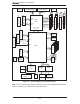
Jumper Description Default Setting
J27/J28 I
2
C Bus to PCI-X/PCI-E Slots Open (Disabled)
J3P 3rd PWR Failure Detect Off (Disabled)
JBT1 CMOS Clear (See Chapter 2)
JCF1 Compact Card Master/Slave Select On (Master)
JPG1 VGA Enable Pins 1-2 (Enabled)
JPL1/ JPL2 GLAN1/GLAN2 Enable Pins 1-2 (Enabled)
JWD (J19) Watch Dog Pins 1-2 (Reset)
Connector Description
ATX PWR (JPW1) Primary 24-Pin ATX PWR Connector
Aux. PWR/CPU PWR +12V 4-pin PWR (JWP2)/+12V 8-pin PWR(JPW3)
Alarm Reset (JAR) Alarm Buzzer Reset
Compact Flash PW(JWF1) Compact Card PWR Connector(*Used if JFC1 is on.)
COM1/COM2 (JCOM1/2) COM1/COM2 Serial Port Connectors
Chassis Intru. (JL1) Chassis Intrusion Header
FAN 1-8 Fans 1-8 (Fan7: CPU Fan1, Fan8: CPU Fan2)
FP CTRL (JF1) Front Control Panel Connector
Floppy (J22) Floppy Disk Drive Connector
GLAN 1/2 (JLAN1/2) G-bit Ethernet Ports
IDE1/IDE2 (Note) IDE1 Hard Drive (JIDE1)/Compact Flash Card (JIDE2)
KB/Mouse (JKM1) PS2 Keyboard/Mouse
Keylock (JK1) Keylock Header
SIMLP (Slot 7) SIMLP (Supermicro Intelligent Management) Add-On
Card Slot Connector
OH LED (JOH1) Overheat LED
Parallel Port (J21) Parallel (Printer) Port
PWR LED/Speaker (JD1) PWR LED(pins1-3)/SpeakerHeader (pins 4-7)
PWR LED (LE1) PWR LED Indicator (Note6 on Pg.1-4)
PSF (JP3) Power Fault (Power Supply Failure: See Chapter 2)
SATA0-SATA5 Intel SATA 0-5 Connectors
SMBus PS (J17) Power System Management (I
2
C) Header
SMB (J18) System Management Bus Header
T-SGPIO 1/2 (J29, J30) Serial General Purpose Input/Output Headers
USB 0/1 (JUSB1) Back Panel USB 0/1
USB 2/3,USB4 (JUSB2/3) Front Panel USB 2/3 (JUSB2), FP USB 4 (JUSB4)
VGA (J15) VGA Connector
WOL (JWOL1) Wake-on-LAN Header
WOR (JWOR1) Wake-on-Ring Header
Note: JIDE2 is for Compact Card Use only. For Compact Card to work properly,
please enable JCF1 by putting a jumper on it and connect JWF1 to a power
supply.
Quick Reference ( X7DBi+)