
Datasheet


Chapter 4: BIOS
4-11
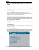
Advanced Chipset Control
Access the submenu to make changes to the following settings.
*Warning: Take Caution when changing the Advanced settings. Incorrect
values entered may cause the system to malfunction. Also, a very high DRAM
frequency or incorrect DRAM timing may cause system instability. When this
occurs, revert the setting to the default setting.
SERR Signal Condition
This setting specifi es the ECC Error conditions that an SERR# is to be asserted.
The options are None, Single Bit, Multiple Bit, and Both.
4GB PCI Hole Granularity
This feature allows you to select the granularity of PCI holes for the PCI slots. If
MTRRs are not enough, this option may be used to reduce MTRR occupation. The
options are: 256 MB, 512 MB, 1GB and 2GB.
Memory Branch Mode
This option determines how the two memory branches operate. System address
space can either be interleaved between the two branches or Sequential from one
branch to another. Mirror mode allows data correction by maintaining two copies
of data in two branches. Single Channel 0 allows a single DIMM population during
system manufacturing. The options are Interleave, Sequential, Mirroring, and
Single Channel 0.
Branch 0 Rank Sparing/Branch 1 Rank Sparing
Select enable to enable the function of memory sparing for Memory Bus Branch
0 or Branch 1 to enhance memory performance. The options are Enabled and
Disabled.
Branch 0 Rank Interleaving/Branch 1 Rank Interleaving
Select enable to enable Interleaved Memory for Memory Bus Branch 0 Rank or
Branch 1 Rank to increase data security. The options for Memory Interleaving are
1:1, 2:1 and 4:1.
Enhanced x8 Detection
Select Enabled to enable Enhanced x8 DRAM UC Error Detection. The options
are Disabled and Enabled.
High Bandwidth FSB
Select Enabled to enable high bandwidth Front Side Bus (FSB). The options are
Enabled and Disabled.