
Datasheet


Chapter 2: Installation
2-7
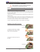
To Install: Insert module vertically and press down until it
snaps into place. Pay attention to the alignment notch at
the bottom.
Figure 2-2. Installing and Removing DIMMs
2 FBD
To Remove:
Use your thumbs to gently
push the release tabs near
both ends of the module.
This should release it from
the slot.
2 FBD Slot
Possible System Memory Allocation & Availability
System Device Size Physical Memory
Remaining (-Available)
(4 GB Total System Memory)
Firmware Hub fl ash memory
(System BIOS)
1 MB 3.99
Local APIC 4 KB 3.99
Area Reserved for the
chipset
2 MB 3.99
I/O APIC (4 Kbytes) 4 KB 3.99
PCI Enumeration Area 1 256 MB 3.76
PCI Express (256 MB) 256 MB 3.51
PCI Enumeration Area 2
(if needed) -Aligned on
256-MB boundary-
512 MB 3.01
VGA Memory 16 MB 2.85
TSEG 1 MB 2.84
Memory available to System
BIOS & OS applications
2.84
JW
O
R
1
C
O
M
2
J7
JB
T
1
JW
O
L1
JP
L1
JP
L2
J30
JL1
JO
H
1
JD
1
Fa
n
2
L
E
1
JF
1
F
P
C
T
R
L
JP
W
1
J1
7
LE
2
S
W
1
J1
1
I2
C
1
I2
C
2
JP
G
1
R
ea
r U
ID
E
S
1
0
0
0
V
id
eo
C
T
R
L
Intel ESB2
(South Bridge)
U
S
B
4
JW
D
JK
1
U
SB
2/3
J1
8
S
M
B
CPU1
JP
W
3
C
O
M
1
V
G
A
LA
N
1
LA
N
2
J2
8
S
X
B
2
: P
C
I-E x8
S
X
B
1
: P
C
I-E
x1
6
P
C
I-X
1
3
3 M
H
z
(North Bridge)
Video M
emory
X7DBU
J29
F
a
n
4
F
a
n
8
C
P
U
FA
N
2
F
a
n
3
F
an
1
2
0
-P
in
M
a
in
P
W
R
JP
W
2
4
-P
in
P
W
R
8
-P
in
P
W
R
F
a
n
7
C
P
U
F
a
n
1
P
W
R
S
M
B
F
a
n
5
F
a
n
6
B
u
zz
er
S
P
1
J9B
2
J9
B
1
J8
B
3
J8
B
2
J8B
1
J7
B
3
J7
B
2
J7
B
1
D
IM
M
4
B
S
G
P
IO
1
S
G
P
IO
2
J2
7
U
IO
P
W
R
LA
N
C
T
R
L
JL
A
N
2
JL
A
N
1
J1
5
JC
O
M
1
JK
M
1
B
a
n
k
1
I-S
A
T
A
0
I-S
A
T
A
1
I-S
A
T
A
2
I-S
A
T
A
3
I-S
A
T
A
4
I-S
A
T
A
5
B
IO
S
J22
Flo
p
p
y
S
IM
S
O
ID
E#
1
CPU2
JP
1
D
IM
M
1
A
D
IM
M
1
B
D
IM
M
2
A
D
IM
M
2
B
D
IM
M
3
A
D
IM
M
3
B
D
IM
M
4
A
B
a
tte
ry
B
an
k2
B
a
n
k3
B
a
n
k
4
K
B
/M
S
U
S
B
0
/1
J5
J1
4
S
I/O
Intel 5000
J9