
Datasheet


2-16
X7DBU/X7DGU User's Manual
J
W
OR1
COM
2
J
7
J
BT
1
JW
O
L1
J
PL1
J
PL2
J
30
J
L1
J
OH1
J
D
1
F
an
2
LE
1
J
F
1
F
P
CT
R
L
J
PW
1
J
17
LE2
SW1
J11
I2C1
I2C2
J
PG
1
Rear UID
E
S
10
00
V
id
e
oCT
RL
Inte
l
E
S
B
2
(S
outh B
ridge
)
US
B4
J
W
D
JK1
US
B2/3
J
1
8
S
M
B
C
P
U1
J
PW
3
COM1
VGA
LAN1
LAN2
J
28
S
XB2: PCI-E x8
S
XB1: PCI-E
x
16
PCI-X
133 MHz
(Nort
hBri
dg
e
)
V
i
d
e
o
M
e
m
or
y
X7DBU
J
29
F
an
4
F
an
8
C
PU
F
A
N2
F
an
3
F
an
1
20
-
Pin Main PW
R
J
PW
2
4-Pin PW
R
8-Pin PW
R
F
an
7
CPU
F
an
1
PW
RS
M
B
F
a
n
5
F
a
n
6
Bu
z
z
e
r
S
P1
J9B2
J9B1
J8B3
J8B2
J8B1
J7B3
J7B2
J7B1
D
IMM
4B
S
GPIO1
S
GPIO2
J
27
U
IO
PW
R
LA
N
C
T
RL
J
LA
N2
J
LA
N
1
J
15
J
COM
1
J
KM1
Bank1
I-
S
A
T
A
0
I-S
A
T
A
1
I-S
A
T
A
2
I-
S
A
T
A
3
I-S
A
T
A
4
I-
S
A
T
A
5
BIOS
J
2
2
Flo
p
p
y
S
IMS
O
ID
E
#
1
C
P
U
2
J
P1
D
IM
M
1A
D
IMM
1B
D
IMM
2A
D
IMM
2
B
D
I
M
M3A
D
IMM3
B
D
IMM
4A
Batt
e
r
y
Bank2
Bank3
Bank4
KB/MS
USB 0/1
J
5
J14
SI/
O
I
ntel 50
00
J
9
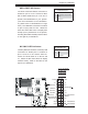
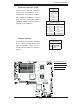
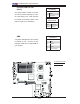
Fan Headers
The X7DBU/X7DGU has eight chassis/system
fan headers (Fan1 to Fan8.) Fan1-Fan6 are
chassis/system fans, while Fan7 and Fan8 are
CPU fans. Fan5-Fan8 are 4-pin fan headers.
Pins 1-3 of the 4-pin fan headers are backward
compatible with the traditional 3-pin fans. The
fan speeds for the 4-pin fans are controlled
by Thermal Management via BIOS Hardware
Monitor in the Advanced Setting. The default
setting is Disabled. See the table on the right
for pin defi nitions. (*Note: all these fans are
4-pin fan connectors. However, Pins 1-3 of
the fan headers are backward compatible with
the traditional 3-pin fans.)
3-Pin Fan Header
Pin Defi nitions
Pin# Defi nition
1 Ground
2 +12V
3 Tachometer
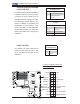
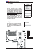
Keylock
The keyboard lock connection is designated
JK1. Utilizing this header allows you to inhibit
any actions made on the keyboard, effectively
"locking" it.
Keylock
Pin Defi nitions
Pin# Defi nition
1 Ground
2 Keylock R-N
B
C
G
F
E
D
A
A. Fan1
B. Fan2
C. Fan3
D. Fan4
E. Fan5
F. F a n6
G.Fan7(CPU Fan1)
H.Fan8(CPU Fan2)
K.Keylock
H
I
4-Pin Fan Header
Pin Defi nitions
Pin# Defi nition
1 Ground
2 +12V
3 Tachometer
4 PWM Signals