
Datasheet

Chapter 2: Installation
2-27
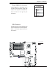
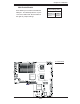
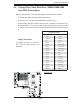
J
W
OR1
CO
M
2
J
7
J
BT1
J
W
O
L1
J
PL1
J
PL2
J
30
J
L1
J
OH1
J
D
1
F
an
2
LE
1
J
F
1
F
P
CT
R
L
J
PW
1
J
17
LE2
SW1
J11
I2C1
I2C2
J
PG
1
Rear UID
E
S
1
0
00
V
id
e
oCT
RL
Inte
l
E
S
B
2
(S
outh B
ridge
)
US
B4
JW
D
J
K1
US
B2/3
J
1
8
S
M
B
C
P
U1
J
PW
3
COM1
VGA
LAN1
LAN2
J
28
S
X
B2: PCI-E x8
S
XB1: PCI-E
x
16
PCI-X
133 MHz
(Nort
hBr
i
dg
e
)
V
i
d
e
o
M
e
m
or
y
X7DBU
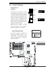
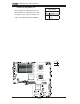
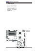
J
29
F
an
4
F
an
8
C
PU F
A
N2
F
an
3
Fan1
20
-
PinMainPW
R
J
PW
2
4-Pin PW
R
8-Pin PW
R
F
an
7
CPU
F
an
1
PW
RS
M
B
F
a
n
5
F
a
n
6
Bu
z
z
e
r
S
P1
J9B2
J9B1
J8B3
J8B2
J8B1
J7B3
J7B2
J7B1
D
IMM
4B
S
GPIO1
S
GPIO2
J
27
U
IO
PW
R
LA
N
C
T
RL
J
LA
N2
J
LA
N
1
J
15
J
COM
1
J
KM1
Bank1
I-
S
A
T
A
0
I-S
A
T
A
1
I-S
A
T
A
2
I-
S
A
T
A
3
I-S
A
T
A
4
I-
S
A
T
A
5
BIOS
J
22
F
lo
p
py
S
IMS
O
ID
E
#
1
C
P
U
2
J
P1
D
IM
M
1A
D
IMM
1B
D
IMM
2A
D
IMM
2
B
D
I
M
M3A
D
IMM3
B
D
IMM
4A
Batt
e
r
y
Bank2
Bank3
Bank4
KB/MS
USB 0/1
J
5
J14
SI/
O
I
ntel 50
00
J
9
GLAN LEDs
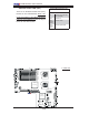
There are two GLAN ports on the moth-
erboard. Each Gigabit Ethernet LAN port
has two LEDs. The yellow LED indicates
activity, while the Link LED may be green,
amber or off to indicate the speed of the
connection. See the tables at right for
more information.
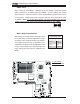
2-7 Onboard Indicators
A
B
A. GLAN Port1 LEDs
B. GLAN Port2 LEDs
Activity
LED
GLAN Activity Indicator
LED Color Defi nition
Off Not Active
Yellow Blinking: Active
GLAN Link Indicator
LED Color Defi nition
Off No Connection or 10 Mbps
Green 100 Mbps
Amber 1 Gbps
Link
LED
(Rear View: When viewing from
the rear side of the system)