
Datasheet


2-32
X7DBU/X7DGU User's Manual
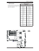
JWOR1
COM2
J7
JBT1
JWOL1
JPL1
JPL2
J30
JL1
JOH1
JD1
Fan2
LE1
JF1
FP CTRL
JPW1
J17
LE2
SW1
J11
I2C1
I2C2
JPG1
Rear UID
ES1000
Video CTRL
Intel ESB2
(South Bridge)
USB4
JWD
JK1
USB2/3
J18
SMB
CPU1
JPW3
COM1
VGA
LAN1
LAN2
J28
SXB2: PCI-E x8
SXB1: PCI-E x16
PCI-X 133 MHz
(North Bridge)
V
id
eo
M
e
m
o
ry
X7DBU
J29
Fan4
Fan8
CPU FAN2
Fan3
Fan1
20-Pin Main PWR
JPW2
4-Pin PWR
8-Pin PWR
Fan7
CPU Fan1
PWR SMB
Fan5
Fan6
Buzzer
SP1
J9B2
J9B1
J8B3
J8B2
J8B1
J7B3
J7B2
J7B1
DIMM4B
SGPIO1
SGPIO2
J27
UIO PWR
LAN
CTRL
JLAN2
JLAN1
J15
JCOM1
JKM1
Bank1
I-SATA0
I-SATA1
I-SATA2
I-SATA3
I-SATA4
I-SATA5
BIOS
J22
Floppy
SIMSO
IDE#1
CPU2
JP1
DIMM1A
DIMM1B
DIMM2A
DIMM2B
DIMM3A
DIMM3B
DIMM4A
Battery
Bank2
Bank3
Bank4
KB/MS
USB 0/1
J5
J14
S I/O
Intel 5000
J9
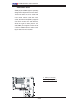
A
B
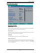
A. SXB1 (the left slot)
B. SXB2 (the right slots)
SXB1/SXB2 Slots
SXB1(J5) and SXB2 (J9) are specially
designed for Supermicro's riser cards.
These two slots are to be used with
riser cards. When used with riser
cards, the left IO slot (SXB1) supports
one PCI-E x8 and one UIO devices;
while the right IO slots (PCI-X: J14
and SXB2) can support a PCI-E x8 or
a PCI-X 133MHz device. Refer to the
layout below for the location.