
User Manual


Chapter 2: Installation
2-21
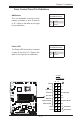
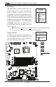
LSI 1068E
NIC4 LED
JBMC1
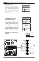
2-6 Connecting Cables
Thissectionprovidesbriefdescriptionsandpin-outdenitionsforonboardheaders
and connectors. Be sure to use the correct cable for each header or connector.
•Forinformationon Backpanel USB and Front Panel USB ports, refer to Page
2-14.
• For information on COM Port 1 and COM Port 2, please see Page 2-16.
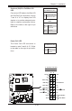
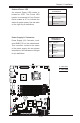
A. 24-Pin ATX Main PWR
B. 8-Pin Processor PWR
A
B
ATX Power 24-pin Connector
PinDenitions(JPW1)
Pin#DenitionPin#Denition
13 +3.3V 1 +3.3V
14 -12V 2 +3.3V
15 COM 3 COM
16 PS_ON 4 +5V
17 COM 5 COM
18 COM 6 +5V
19 COM 7 COM
20 Res (NC) 8 PWR_OK
21 +5V 9 5VSB
22 +5V 10 +12V
23 +5V 11 +12V
24 COM 12 +3.3V
(Required)
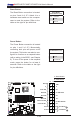
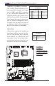
12V 8-pin Power Connec-
torPinDenitions
PinsDenition
1 through 4 Ground
5 through 8 +12V
ATX Main PWR & CPU PWR
Connectors
The 24-pin main power connector
(JPW1) is used to provide power to
the motherboard. The 8-pin CPU PWR
connector (JPW2) is also required for
the processor. These power connec-
torsmeettheSSIEPS12Vspecica-
tion. See the table on the right for pin
denitions.