X9SRi X9SRi-F X9SRi-3F X9SRE X9SRE-F X9SRE-3F USER’S MANUAL Revision 1.
The information in this User’s Manual has been carefully reviewed and is believed to be accurate. The vendor assumes no responsibility for any inaccuracies that may be contained in this document, makes no commitment to update or to keep current the information in this manual, or to notify any person or organization of the updates. Please Note: For the most up-to-date version of this manual, please see our web site at www.supermicro.com. Super Micro Computer, Inc.
Preface Preface This manual is written for system integrators, PC technicians and knowledgeable PC users. It provides information for the installation and use of the X9SRi/X9SRE Motherboard Series motherboard. About This Motherboard The X9SRi/X9SRE Motherboard Series supports a single Intel® E5-1600/ E5-2600 series processor (2011-pin, Socket R). With the Intel® C600 series chipset built in, the X9SRi/X9SRE Motherboard series offers top-of-the-line system performance and storage capability.
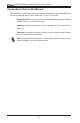
X9SRi/X9SRE Motherboard Series User’s Manual Conventions Used in the Manual: Special attention should be given to the following symbols for proper installation and to prevent damage done to the components or injury to yourself: Danger/Caution: Instructions to be strictly followed to prevent catastrophic system failure or to avoid bodily injury Warning: Critical information to prevent damage to the components or data loss.
Contacting Supermicro 1-4 Contacting Supermicro Headquarters Address: Super Micro Computer, Inc. 980 Rock Ave. San Jose, CA 95131 U.S.A. Tel: +1 (408) 503-8000 Fax: +1 (408) 503-8008 Email: marketing@supermicro.com (General Information) support@supermicro.com (Technical Support) Web Site: www.supermicro.com Europe Address: Super Micro Computer B.V. Het Sterrenbeeld 28, 5215 ML 's-Hertogenbosch, The Netherlands Tel: +31 (0) 73-6400390 Fax: +31 (0) 73-6416525 Email: sales@supermicro.
X9SRi/X9SRE Motherboard Series User’s Manual Table of Contents Preface About This Motherboard................................................................................................. iii Manual Organization...................................................................................................... iii Conventions Used in the Manual:..................................................................................iv 1-4 Contacting Supermicro................................................
Table of Contents Removing Memory Modules............................................................................ 2-8 Memory Support............................................................................................... 2-9 Memory Population Guidelines...................................................................... 2-10 2-4 Motherboard Installation..................................................................................2-11 Tools Needed............................................
X9SRi/X9SRE Motherboard Series User’s Manual 2-7 Jumper Settings............................................................................................. 2-30 Explanation of Jumpers................................................................................. 2-30 LAN Port Enable/Disable (JPL1~2)........................................................... 2-30 CMOS Clear (JBT1).................................................................................. 2-31 PCI-E Slot SMB Enable (JI2C1/JI2C2)..
Table of Contents Chapter 4 BIOS 4-1 Introduction....................................................................................................... 4-1 Starting BIOS Setup Utility............................................................................... 4-1 How To Change the Configuration Data.......................................................... 4-1 How to Start the Setup Utility.......................................................................... 4-2 4-2 Main Setup..................
X9SRi/X9SRE Motherboard Series User’s Manual Power Technology....................................................................................... 4-7 EIST............................................................................................................. 4-7 Turbo Mode................................................................................................. 4-7 C1E Support................................................................................................
Table of Contents Serial-ATA Controller 0~1...........................................................................4-11 AHCI Mode.................................................................................................4-11 Aggressive Link Power Management.........................................................4-11 Port 0~5 Hot Plug..................................................................................... 4-12 Staggered Spin Up...........................................................
X9SRi/X9SRE Motherboard Series User’s Manual 4-4 Event Logs..................................................................................................... 4-17 Change SmBIOS Event Log Settings......................................................... 4-17 Smbios Event Log..................................................................................... 4-17 Runtime Error Logging Support................................................................ 4-17 Memory Correction Error Threshold.........
Table of Contents Appendix A BIOS Error Beep Codes A-1 BIOS Error Beep Codes..................................................................................A-1 Appendix B Software Installation Instructions B-1 Installing Software Programs...........................................................................B-1 B-2 Configuring SuperDoctor III.............................................................................B-2 Appendix C UEFI BIOS Recovery Instructions An Overview to the UEFI BIOS...
X9SRi/X9SRE Motherboard Series User’s Manual Notes xiv
Chapter 1: Introduction Chapter 1 Introduction 1-1 Overview Checklist Congratulations on purchasing your computer motherboard from an acknowledged leader in the industry. Supermicro boards are designed with the utmost attention to detail to provide you with the highest standards in quality and performance. Please check that the following items have all been included with your motherboard. If anything listed here is damaged or missing, contact your retailer.
X9SRi/X9SRE Motherboard Series User’s Manual X9SRE Motherboard Series Image Note: All graphics shown in this manual were based upon the latest PCB Revision available at the time of publishing of the manual. The motherboard you've received may or may not look exactly the same as the graphics shown in this manual.
Chapter 1: Introduction X9SRi Motherboard Series Image Note: All graphics shown in this manual were based upon the latest PCB Revision available at the time of publishing of the manual. The motherboard you've received may or may not look exactly the same as the graphics shown in this manual.
12 JCF1:Compact Flash ON: MASTER OFF: SLAVE 3 JWF1 3 1 24 1 4 COM1 3 4 4 PWRI2C FAN1 JPI2C1 + 1 JL1 JD1 JWD1 1-4 FAN2 4 Jumpers not indicated are for testing only. 1 7 8 8 • SP1 4 " " indicates the location of "Pin 1".
Chapter 1: Introduction X9SRi/X9SRE Motherboard Series Quick Reference UID LED JLAN2 JI2C1 JI2C2 UID_LED UID UID_SW 1 2 JVGA FAN4 JCOM1 COM1 1 JCOM2 COM2 LAN1 1 JPL2 JPL1 JPG1: VGA 1-2 Enable 2-3 Disable P1-DIMM4A P1-DIMM4B JPG1 Connect to IPMI PCIE5 JI2C1/JI2C2 I2C Bus for PCI slot ON: ENABLE OFF:DISABLE Tested to Comply With FCC Standards FOR HOME OR OFFICE USE JI2C1 JI2C2 CLOSE 1st PCIE4 SLOT6 PCI-E 3.
X9SRi/X9SRE Motherboard Series User’s Manual X9SRi/X9SRE Motherboard Series Headers/Connectors Connector Description JCOM1, JCOM2 COM1 Backpanel Serial Port, COM2 Serial Port Header JIPMB1 System Management Bus Header for the IPMI Slot JTPM1 Trusted Platform Module (TPM) Header JUSB 4/5, 6/7, 8/9 Front Accessible USB Connections (via 3 Headers) JOH1 Overheat LED/Fan Fail 3-SGPIO1, 3-SGPIO2 Serial General Purpose I/O Headers for SAS JUSB2 Internal Type A USB port SCU0~7 Internal Serial-Attac
Chapter 1: Introduction Motherboard Features CPU Single Intel® E5-1600/E5-2600 series processor (LGA 2011 pin, Socket-R) Memory Eight (8) DIMM slots support up to 256GB of DDR3, ECC RDIMM memory or 64GB of DDR3 Unbuffered, non-ECC UDIMM memory, up to 1600MHz..
X9SRi/X9SRE Motherboard Series User’s Manual Keyboard/Mouse One (1) PS/2 KB/Mouse combo port on the I/O backpanel Serial (COM) Ports Two (2) Fast UART 16550 connections: one 9-pin RS-232 port (Backpanel COM1 port) and one header (COM2) Super I/O Winbond Super I/O NCT6776F BIOS 64 Mb SPI AMI BIOS® SM Flash BIOS Play and Plug APM 1.2, DMI 2.3, PCI 2.2, ACPI 1.0/2.0, USB Keyboard and SMBIOS 2.
Chapter 1: Introduction X9SRi/X9SRE Motherboard Features Comparison Model SAS SATA (2.0/3.
X9SRi/X9SRE Motherboard Series User’s Manual X9SRi/X9SRE Motherboard Series Block Diagram #0-8 #0-7 #0-6 #0-5 #3C/D #3A/B #1B #1A DMI2 PCI-E X4 G3 PCI-E X16 LAN#1/2 RJ45 PCI-E X8 G3 DMI2 4GB/s PCI-E X16 G3 PCI-E X8 G3 SLOT 4 DDRIII DDRIII #2 800/1066/1333 Intel® E5-1600/E52600 Series Processor 8 SNB CORE DDR-III MAX 130W 800/1066/1333 PCI-E X16 SLOT 6 #0-4 #0-3 #0-2 #0-1 VR12 6 PHASE i350/x540 RJ45 #5 #4 #3 #2 PCI-E X4 G2 #1/2/3/4 #1 #0 PCH SLOT 1/2/3 PCI-X PXH 6.
Chapter 1: Introduction 1-2 Chipset Overview The Intel® C600 series is a single chip solution that is designed for dedicated servers and workstations. It supports high-speed SAS, SATA and advanced requirements for Intel Xeon platforms.
X9SRi/X9SRE Motherboard Series User’s Manual 1-3 Special Features Recovery from AC Power Loss Basic I/O System (BIOS) provides a setting for you to determine how the system will respond when AC power is lost and then restored to the system. You can choose for the system to remain powered off (in which case you must press the power switch to turn it back on), or for it to automatically return to a power-on state. See the Advanced BIOS Setup section to change this setting.
Chapter 1: Introduction the Windows OS environment or used with Supero Doctor II in Linux. Supero Doctor is used to notify the user of certain system events. For example, you can also configure Supero Doctor to provide you with warnings when the system temperature, CPU temperatures, voltages and fan speeds go beyond predefined thresholds. 1-5 ACPI Features ACPI stands for Advanced Configuration and Power Interface.
X9SRi/X9SRE Motherboard Series User’s Manual 8-pin (JPW2) power connectors on the motherboard. Failure in doing so will void the manufacturer warranty on your power supply and motherboard. 2. To provide adequate power to SATA devices, please connect the SATA DOM PWR connector (JWF1) to the power supply. It is strongly recommended that you use a high quality power supply that meets ATX power supply Specification 2.02 or above. It must also be SSI compliant.
Chapter 2: Installation Chapter 2 Installation 2-1 Static-Sensitive Devices Electrostatic-Discharge (ESD) can damage electronic components. To avoid damaging your system board, it is important to handle it very carefully. The following measures are generally sufficient to protect your equipment from ESD. Precautions • Use a grounded wrist strap designed to prevent static discharge. • Touch a grounded metal object before removing the board from the antistatic bag.
X9SRi/X9SRE Motherboard Series User’s Manual 2-2 Processor and Heatsink Installation Warning: When handling the processor package, avoid placing direct pressure on the label area. Important: Always connect the power cord last, and always remove it before adding, removing or changing any hardware components. Make sure that you install the processor into the CPU socket before you install the CPU heatsink. If you buy a CPU separately, make sure that you use an Intel-certified multi-directional heatsink only.
Chapter 2: Installation 2. Press the second load lever labeled 'Close 1st' to release the load plate which covers the CPU socket from its locking position. Press down on Load Lever 'Close 1st' 1 WA R NI NG 2 Pull lever away from the socket ! WA R NI OP EN NG ! 1st OP EN 1st 3. With the 'Close 1st' lever fully retracted, gently push down on the 'Open 1st' lever to open the load plate. Lift the load plate to open it completely.
X9SRi/X9SRE Motherboard Series User’s Manual Installing the LGA2011 Processor WA R NIN G! 1. With the LGA 2011 socket open, remove the 'WARNING' plastic cap using your fingers. Socket Keys CPU Keys 2. Use your thumb and index finger to hold the CPU on its edges. Align the CPU keys (semi-circle cutouts) against the socket keys. Warning: You can only install the CPU inside the socket in one direction. Make sure that it is properly inserted into the CPU socket before closing the load plate.
Chapter 2: Installation 3. Once it is aligned, carefully lower the CPU straight down into the socket. (Do not drop the CPU on the socket. Do not move the CPU horizontally or vertically. 4. Do not rub the CPU against the surface or against any pins of the socket to avoid damaging the CPU or the socket.) 5. With the CPU inside the socket, inspect the four corners of the CPU to make sure that the CPU is properly installed. 6. To close and lock the socket, close the load plate with the CPU.
X9SRi/X9SRE Motherboard Series User’s Manual Installing a Passive CPU Heatsink 1. Do not apply any thermal grease to the heatsink or the CPU die -- the required amount has already been applied. 2. Place the heatsink on top of the CPU so that the four mounting holes are aligned with those on the Motherboard's and the Heatsink Bracket underneath. 3. Screw in two diagonal screws (i.e., the #1 and the #2 screws) until just snug (-do not over-tighten the screws to avoid possible damage to the CPU.) 4.
Chapter 2: Installation Removing the Heatsink Warning: We do not recommend that the CPU or the heatsink be removed. However, if you do need to uninstall the heatsink, please follow the instructions below to uninstall the heatsink to prevent damage done to the CPU or the CPU socket. 1. Unscrew the heatsink screws from the motherboard in the sequence as shown in the illustration below. 2. Gently wriggle the heatsink to loosen it from the CPU. (Do not use excessive force when wriggling the heatsink!!) 3.
X9SRi/X9SRE Motherboard Series User’s Manual 2-3 Installing DDR3 Memory Note: Check the Supermicro website for recommended memory modules. CAUTION Exercise extreme care when installing or removing DIMM modules to prevent any possible damage.
Chapter 2: Installation Memory Support T h e X9 S R i / X9 S R E m o t h e r b o a r d s e r i e s s u p p o r t s u p t o 2 5 6 G B o f 1600/1066/1333/1600 MHz ECC/Non-ECC DDR3 DIMMs in eight (8) memory slots (UDIMM/RDIMM). Populating these DIMM modules with a pair of memory modules of the same type and same size will result in interleaved memory, which will improve memory performance.
X9SRi/X9SRE Motherboard Series User’s Manual Memory Population Guidelines When installing memory modules, the DIMM slots should be populated in the following order: DIMMA1, DIMMB1, DIMMC1, DIMMD1 then DIMMA2, DIMMB2, DIMMC2, DIMMD2. • Always use DDR3 DIMM modules of the same size, type and speed. • Mixed DIMM speeds can be installed. However, all DIMMs will run at the speed of the slowest DIMM. • The motherboard will support 1 ,3 ,5 ,or 7 modules.
Chapter 2: Installation 2-4 Motherboard Installation All motherboards have standard mounting holes to fit different types of chassis. Make sure that the locations of all the mounting holes for both motherboard and chassis match. Although a chassis may have both plastic and metal mounting fasteners, metal ones are highly recommended because they ground the motherboard to the chassis. Make sure that the metal standoffs click in or are screwed in tightly.
X9SRi/X9SRE Motherboard Series User’s Manual Installing the Motherboard 1. Install the I/O shield into the chassis. 2. Locate the mounting holes on the motherboard. 3. Locate the matching mounting holes on the chassis. Align the mounting holes on the motherboard against the mounting holes on the chassis. 4. Install standoffs in the chassis as needed. 5. Install the motherboard into the chassis carefully to avoid damaging motherboard components. 6.
Chapter 2: Installation 2-5 Connectors/IO Ports The I/O ports are color coded in conformance with the PC 99 specification. See the figure below for the colors and locations of the various I/O ports.
X9SRi/X9SRE Motherboard Series User’s Manual ATX PS/2 Keyboard/Mouse Ports The ATX PS/2 keyboard and PS/2 mouse are located next to the Back Panel USB Ports 0/1 on the motherboard. See the table at right for pin definitions.
Chapter 2: Installation Universal Serial Bus (USB) Back Panel USB Ports Pin Definitions Two Universal Serial Bus ports (USB 0/1) are located on the I/O back panel. In addition, six USB headers (USB 4/5, USB 6/7, USB 8/9) are used to provide front chassis access. There is also one Type A internal USB port located on USB 2. (USB Cables are not included). See the tables on the right for pin definitions.
X9SRi/X9SRE Motherboard Series User’s Manual Ethernet Ports Two Ethernet ports (LAN1/LAN2) are located next to the VGA port on the I/O Backpanel. In addition, an IPMI Dedicated LAN port is also located above USB 0/1 to provide a dedicated network connection for IPMI 2.0 on the X9SRi-3F and X9SRE-3F motherboard.
Chapter 2: Installation Serial Ports Serial Port Pin Definitions (COM1/COM2) A COM Port (COM1) is located on the I/O backpanel, and another Serial Pin # header (COM2) is located towards the rear of Slot 1 to provide front serial access. See the table on the right for pin definitions. Definition Pin # Definition 1 DCD 6 DSR 2 RXD 7 RTS 3 TXD 8 CTS 4 DTR 9 RI 5 Ground 10 Ground 1. COM1 2.
X9SRi/X9SRE Motherboard Series User’s Manual Video Port A Video (VGA) port is located next to the COM Port on the I/O backpanel. This port is used to provide a connection for video and graphics display. Refer to the board layout below for the location.
Chapter 2: Installation Front Control Panel JF1 contains header pins for various buttons and indicators that are normally located on a control panel at the front of the chassis. These connectors are designed specifically for use with Supermicro server chassis. See the figure below for the descriptions of the various control panel buttons and LED indicators. Refer to the following section for descriptions and pin definitions.
X9SRi/X9SRE Motherboard Series User’s Manual Front Control Panel Pin Definitions Power LED Pin Definitions (JF1) Power LED The Power LED connection is located on pins 15 and 16 of JF1. Refer to the table on the right for pin definitions. Pin# Definition 15 +3.3V 16 Ground HDD LED HDD LED Pin Definitions (JF1) The HDD LED connection is located on pins 13 and 14 of JF1. Attach a cable here to indicate the status of HDD-related activities, including IDE, SATA activities.
Chapter 2: Installation NIC1/NIC2 (LAN1/LAN2) LAN1/LAN2 LED Pin Definitions (JF1) The NIC (Network Interface Controller) LED connection for LAN port 1 is located Pin# on pins 11 and 12 of JF1, and the LED connection for LAN Port 2 is on Pins 9 and 10. NIC1 LED and NIC2 LED are 2-pin NIC LED headers. Attach NIC LED cables to NIC1 and NIC2 LED indicators to display network activities. Refer to the table on the right for pin definitions.
X9SRi/X9SRE Motherboard Series User’s Manual NMI Button NMI Button Pin Definitions (JF1) The non-maskable interrupt button header is located on pins 19 and 20 Pin# Definition of JF1. Refer to the table on the right for pin definitions. 19 Control 20 Ground Reset Button The Reset Button connection is located on pins 3 and 4 of JF1. Attach it to a hardware reset switch on the computer case to reset the system. Refer to the table on the right for pin definitions.
Chapter 2: Installation 2-6 Connecting Cables & Optional Devices This section provides brief descriptions and pin-out definitions for onboard headers and connectors. Be sure to use the correct cable for each header or connector. ATX Power 24-pin Connector Pin Definitions (JPW1) ATX Main PWR (JPW1) & CPU PWR Connectors (JPW2) The 24 - pin main power connector (JPW1) is used to provide power to the motherboard. The 8-pin CPU PWR connector (JPW2) is also required for the processor.
X9SRi/X9SRE Motherboard Series User’s Manual Fan Headers (FAN1~4, FANA) Fan Header Pin Definitions The X9SRi/X9SRE series has five fan headers (Fan 1~Fan 4 and Fan A). These fans are 4-pin fan headers. Pins 1-3 of these fan headers are backward compatible with the traditional 3-pin fans. However, the fan speed control setting in the BIOS Hardware Monitoring section will only work with 4-pin fans. This allows the BIOS to automatically set fan speeds based on the system temperature.
Chapter 2: Installation Speaker (JD1) Speaker Connector Pin Definitions On the JD1 header, Pins 6~7 are used for the internal speaker. Close Pins 6~7 with a jumper or cap to use the onboard speaker. If you wish to use an external speaker, attach the external speaker's cable to Pins 1~4. See the table on the right for pin definitions.
X9SRi/X9SRE Motherboard Series User’s Manual Power Supply I2C (JPI2C1) PWR Supply I2C Pin Definitions The Power Supply I2C Connector, located at JPI2C, monitors the status of the power supply, fan and system temperature. See the table on the right for pin definitions. DOM PWR Connector (JSD1) The Disk-On-Module (DOM) power connector, located at JSD1, provides 5V (Gen1/Gen) power to a solid_state DOM storage device connected to one of the SATA ports. See the table on the right for pin definitions.
Chapter 2: Installation T-SGPIO 1/2 & 3-SGPIO 1/2 Headers Serial_Link-SGPIO Pin Definitions Two T-SGPIO (Serial-Link General Purpose Input/Output) headers are located next to the I-SATA Ports on the motherboard. Additionally, two 3-SGPIO ports (for SAS) are also located next to JUSB 8/9 . These headers are used to communicate with the enclosure management chip in the system. See the table on the right for pin definitions. Refer to the board layout below for the locations of the headers.
X9SRi/X9SRE Motherboard Series User’s Manual Unit ID Switch (UID SW) UID Switch The rear UID switch, the rear UID LED and front UID LED on JF1 are designed to work together. When the user pushes the rear UID switch, the blue backpanel UID LED and front UID LED will turn on. Push the rear UID switch again to turn off UID LED and the front UID LED. This provides easy identification of a system unit that may be in need of service.
12 24 4 JCF1:Compact Flash ON: MASTER OFF: SLAVE 3 JWF1 3 1 JVR2 1 1 COM1 4 2 Ground 3 Data 4 No Connection FAN1 4 4 PWRI2C 1 FAN2 JL1 JD1 JWD1 1 JPI2C1 + 1 T-SGPIO1 T-SGPIO2 7 8 8 SAS4 I-SATA4 CHASSIS INTRUSION 1 I-SATA5 SP1 3 3 I-SATA0 I-SATA1 1 JCF1 1 4 4 2-29 C A JF1 7 1 3 20 1 1 2 MH7 7 Clock 5 Compact Flash Power 1 I-Button Header 1 1 JPW2 JPW2 JPW1 JWD1:Watch Dog 1-2:RST 2-3:NMI JD1: 1-3: PWR LED 4-7: SPEAKER JBT1 1 JF1 NMI X PWR LED HD
X9SRi/X9SRE Motherboard Series User’s Manual 2-7 Jumper Settings Explanation of Jumpers To modify the operation of the motherboard, jumpers can be used to choose between optional settings. Jumpers create shorts between two pins to change the function of the connector. Pin 1 is identified with a square solder pad on the printed circuit board. Note: On two pin jumpers, "Closed" means the jumper is on, and "Open" means the jumper is off the pins.
Chapter 2: Installation CMOS Clear (JBT1) JBT1 is used to clear CMOS. Instead of pins, this "jumper" consists of contact pads to prevent accidental clearing of CMOS. To clear CMOS, use a metal object such as a small screwdriver to touch both pads at the same time to short the connection. Always remove the AC power cord from the system before clearing CMOS. Important: For an ATX power supply, you must completely shut down the system, remove the AC power cord and then short JBT1 to clear CMOS.
X9SRi/X9SRE Motherboard Series User’s Manual VGA Enable (JPG1) VGA Enable/Disable Jumper Settings (JPG1) JPG1 allows you to enable or disable the onboard VGA connector. The default position is on pins 1 and 2 to enable VGA. See the table on the right for jumper settings.
Chapter 2: Installation USB Wake-Up (JPUSB1) USB 0/1 Wake-up Enable Jumper Settings Use the jumper JPUSB1 to "wake-up" your system by pressing a key on a USB keyboard or clicking the USB mouse connected to the backpanel USB Ports 0/1. JPUSB1 is used together with a USB Wake-Up feature in the BIOS. Enable this jumper and the USB support in the BIOS to wake up your system via USB devices.
X9SRi/X9SRE Motherboard Series User’s Manual BIOS Recovery (JPBIOS1) BIOS Recovery Jumper Settings The BIOS Recovery (JPBIOS1) is used to enable or disable the BIOS Recovery feature of the motherboard. Install the jumper on pins 1-2 to begin the recovery process. Pin# Definition 1-2 Normal (Default) 2-3 Recover ME Recovery (JPME1) ME Recovery Jumper Settings ME Recovery (JPME1) is used to enable or disable the ME Recovery feature of the motherboard.
Chapter 2: Installation 2-8 Onboard Indicators LAN Link LED LAN Port LEDs The LAN ports are located on the I/O backpanel of the motherboard. Each Ethernet LAN port has two LEDs. A blinking Activity LED indicates there is data passing through the port, while the Link LED may be green, amber, or off to indicate the speed of the connection. See the tables at right for more information.
X9SRi/X9SRE Motherboard Series User’s Manual Rear Unit ID LED (UID LED) Rear UID LED LED Settings The rear Unit ID LED is located at UID LED on the backpanel. This LED is used in conjunction with the rear UID switch to provide easy identification of a system that might be in need of service. Blue: Solid IPMI Heartbeat LED (DP3) UID Toggled On IPMI Heartbeat LED Indicator LED Settings The IPMI Heartbeat LED is located at DP3. When DP3 blinks, the IPMI feature is functioning properly.
Chapter 2: Installation 2-9 SATA and SAS Connections SATA/SAS Connections SATA/SAS Connectors Pin Definitions Six Serial ATA (SATA) connectors (I-SATA 0~5) are located on the motherboard. I-SATA 0/1 supports data transfer rates of up to 6Gb/s (SATA 3.0), while I-SATA 2~5 supports data transfer rates of up to 3Gb/s (SATA 2.0). Please see the pin definitions on the right table.
X9SRi/X9SRE Motherboard Series User’s Manual Notes 2-38
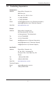
Chapter 3: Troubleshooting Chapter 3 Troubleshooting 3-1 Troubleshooting Procedures Use the following procedures to troubleshoot your system. If you have followed all of the procedures below and still need assistance, refer to the ‘Technical Support Procedures’ and/or ‘Returning Merchandise for Service’ section(s) in this chapter. Always disconnect the AC power cord before adding, changing or installing any hardware components. Before Power On 1. Make sure that the Standby is not on.
X9SRi/X9SRE Motherboard Series User’s Manual No Video 1. If the power is on, but you have no video--in this case, you will need to remove all the add-on cards and cables first. 2. Use the speaker to determine if any beep codes exist. (Refer to Appendix A for details on beep codes.) 3. Remove all memory modules and turn on the system. (If the alarm is on, check the specs of memory modules, reset the memory or try a different one.) Memory Errors 1.
Chapter 3: Troubleshooting 3-2 Technical Support Procedures Before contacting Technical Support, please make sure that you have followed all the steps listed below. Also, Note that as a motherboard manufacturer, Supermicro does not sell directly to end users, so it is best to first check with your distributor or reseller for troubleshooting services. They should know of any possible problem(s) with the specific system configuration that was sold to you. 1.
X9SRi/X9SRE Motherboard Series User’s Manual 3-3 Frequently Asked Questions Question: What type of memory does my motherboard support? Answer: Please see Section 2-3 for a comprehensive answer. Question: How do I update my BIOS? Answer: It is recommended that you do not upgrade your BIOS if you are not experiencing any problems with your system. Updated BIOS files are located on our website at http://www.supermicro.com/support/bios/.
Chapter 3: Troubleshooting Question: Why do I get an error message “IASTOR.SYS read error” and "press F6 to install Intel RAID driver" when installing Windows on my motherboard? Answer: To solve this issue, disable the IPMI jumper. Another solution is to use a USB floppy drive instead of the onboard floppy drive. For the IPMI jumper location, please check Chapter 1.
X9SRi/X9SRE Motherboard Series User’s Manual 3-4 Battery Removal and Installation Battery Removal Battery Battery Lock To remove the onboard battery, follow the steps below: 1. Power off your system and unplug your power cable. Battery Holder 2. Locate the onboard battery as shown below. 3. Using a tool such as a pen or a small screwdriver, push the battery lock outwards to unlock it. Once unlocked, the battery will pop out from the holder. 4. Remove the battery.
Chapter 3: Troubleshooting 3-5 Returning Merchandise for Service A receipt or copy of your invoice marked with the date of purchase is required before any warranty service will be rendered. You can obtain service by calling your vendor for a Returned Merchandise Authorization (RMA) number. For faster service, you may also obtain RMA authorizations online (http://www.supermicro. com/support/rma/).
X9SRi/X9SRE Motherboard Series User’s Manual Notes 3-8
Chapter 4: AMI BIOS Chapter 4 BIOS 4-1 Introduction This chapter describes the AMI BIOS Setup Utility for the X9SRi/X9SRE Motherboard Series. The AMI ROM BIOS is stored in a Flash EEPROM and can be easily updated. This chapter describes the basic navigation of the AMI BIOS Setup Utility setup screens. Note: For instructions on BIOS recovery, please refer to the instruction guide posted at http://www.supermicro.com/support/manuals/.
X9SRi/X9SRE Motherboard Series User’s Manual How to Start the Setup Utility Normally, the only visible Power-On Self-Test (POST) routine is the memory test. As the memory is being tested, press the key to enter the main menu of the AMI BIOS Setup Utility. From the main menu, you can access the other setup screens. An AMI BIOS identification string is displayed at the left bottom corner of the screen, below the copyright message.
Chapter 4: AMI BIOS System Overview: The following BIOS information will be displayed: System Time/System Date Use this option to change the system time and date. Highlight System Time or System Date using the arrow keys. Enter new values through the keyboard. Press the key or the arrow keys to move between fields. The date must be entered in Day MM/DD/YY format. The time is entered in HH:MM:SS format. (Note: The time is in the 24-hour format. For example, 5:30 P.M. appears as 17:30:00.
X9SRi/X9SRE Motherboard Series User’s Manual 4-3 Advanced Setup Configurations Use the arrow keys to select Boot Setup and hit to access the submenu items: BOOT Feature Quiet Boot This option allows the bootup screen options to be modified between POST messages or the OEM logo. Select Disabled to display the POST messages. Select Enabled to display the OEM logo instead of the normal POST messages. The options are Enabled and Disabled.
Chapter 4: AMI BIOS 19 at boot and allow the drives that are attached to these host adaptors to function as bootable disks. If this item is set to Disabled, the ROM BIOS of the host adaptors will not capture Interrupt 19, and the drives attached to these adaptors will not function as bootable devices. The options are Enabled and Disabled. Watch Dog Function If enabled, the Watch Dog Timer will allow the system to reboot when it is inactive for more than 5 minutes. The options are Enabled and Disabled.
X9SRi/X9SRE Motherboard Series User’s Manual Active Processor Cores Set to Enabled to use a processor's Second Core and beyond. (Please refer to Intel's web site for more information.) The options are All and 1. Limit CPUID Maximum This feature allows the user to set the maximum CPU ID value. Enable this function to boot the legacy operating systems that cannot support processors with extended CPUID functions. The options are Enabled and Disabled (for the Windows OS.).
Chapter 4: AMI BIOS Intel® Virtualization Technology (Available when supported by the CPU) Select Enabled to use the feature of Virtualization Technology to allow one platform to run multiple operating systems and applications in independent partitions, creating multiple "virtual" systems in one physical computer. The options are Enabled and Disabled. Note: If there is any change to this setting, you will need to power off and restart the system for the change to take effect.
X9SRi/X9SRE Motherboard Series User’s Manual Long duration maintained - this is the time in milliseconds where the Long Duration Power Limit is maintained. Short duration power limit - During Turbo Mode, the system may exceed the processor's default power setting and exceed the Short Duration Power limit. By increasing this value, the processor can provide better performance for a short duration.
Chapter 4: AMI BIOS DIMM Configuration Memory Configuration This section displays memory status such as Current Memory Mode, Memory Speed, Mirroring and Sparing information. DIMM Information This feature displays information regarding the installed memory. Memory Mode The only option is Independent, a feature that allows for all DIMMs to be available to the operating system.
X9SRi/X9SRE Motherboard Series User’s Manual Demand Scrub Demand Scrubbing is a process that allows the CPU to correct correctable memory errors found on a memory module. When the CPU or I/O issues a demand-read command, and the read data from memory turns out to be a correctable error, the error is corrected and sent to the requestor (the original source). Memory is updated as well. Select Enabled to use Demand Scrubbing for ECC memory correction. The options are Enabled and Disabled.
Chapter 4: AMI BIOS Port 60/64 Emulation This feature enables I/O port 60h/64h emulation support. This should be enabled for complete USB keyboard legacy support for non-USB aware Operating Systems. The options are Enabled, and Disabled. EHCI Hand-Off This item is for Operating Systems that does not support Enhanced Host Controller Interface (EHCI) hand-off. When enabled, EHCI ownership change will be claimed by the EHCI driver. The settings are Enabled and Disabled.
X9SRi/X9SRE Motherboard Series User’s Manual Port 0~5 Hot Plug Set this item to Enabled to enable hot-plugging for the particular port. The options are Enabled and Disabled. Staggered Spin Up Set this item to Enabled to enable Staggered Spin-up support. The options are Enabled and Disabled. RAID Mode The following items are displayed when RAID Mode is selected: Port 0~5 Hot Plug Set this item to Enabled to enable hot-plugging for the particular port. The options are Enabled and Disabled.
Chapter 4: AMI BIOS Above 4G Decoding Set this item to Enabled to activate 64-bit capable devices to be decoded above the 4G address space. This works only if the system supports 64-bit PCI decoding. The options are Enabled and Disabled. PERR# Generation Set this item to Enabled to allow PCI devices to generate PERR# error codes. The options are Enabled and Disabled. SERR# Generation Set this item to Enabled to allow PCI devices to generate SERR# error codes. The options are Enabled and Disabled.
X9SRi/X9SRE Motherboard Series User’s Manual Load Onboard SAS Option ROM This feature selects whether to load the SAS option ROM. The options Enabled and Disabled. VGA Priority This option allows the user to specify which graphics controller to be used as the primary boot device. The options are Onboard and Offboard. Super IO Device Configuration Serial Port 1 Configuration / Serial Port 2 Configuration Serial Port 1 / Serial Port 2 Select Enabled to enable the onboard serial port.
Chapter 4: AMI BIOS Serial Port Console Redirection COM1, COM2, SOL Console Redirection Use this feature to enable console redirection for COM1, COM2, and SOL ports. The options are Enabled and Disabled. The default for COM1 and COM2 is Disabled. The default for SOL is Enabled. Console Redirection Settings Configure the following options for the Console Redirection Settings.
X9SRi/X9SRE Motherboard Series User’s Manual Bits per Second (BPS): 9600, 19200, 57600, or 115200 Flow Control: None, Hardware RTS/CTS, Software Xon/Xoff Data Bits: 8 or 7 Parity: None, Even, Odd, Mark, or Space Stop Bits: 1 or 2 ACPI Settings Use this feature to configure Advanced Configuration and Power Interface (ACPI) power management settings for your system.
Chapter 4: AMI BIOS 4-4 Event Logs Change SmBIOS Event Log Settings Smbios Event Log Change this item to enable or disable all features of the Smbios Event Logging during boot. The options are Enabled and Disabled. Runtime Error Logging Support Change this item to enable or disable runtime error logging. The options are Enabled and Disabled. Memory Correction Error Threshold Change this item to define the system's memory correction error threshold. Directly enter a numeric value, default is 10.
X9SRi/X9SRE Motherboard Series User’s Manual Log System Boot Event This option toggles the System Boot Event logging to enabled or disabled. The options are Disabled and Enabled. MECI The Multiple Event Count Increment (MECI) counter counts the number of occurences a duplicate event must happen before the MECI counter is incremented. This is a numeric value. The default value is 1.
Chapter 4: AMI BIOS 4-5 IPMI (X9SRi-F, X9SRi-3F, X9SRE-F, X9SRE-3F Only) Intelligent Platform Management Interface (IPMI) is a set of common interfaces that IT administrators can use to monitor system health and to manage the system as a whole. For more information on the IPMI specifications, please visit Intel's website at www.intel.com. System Event Log This feature is used to change the Sytem Event Log (SEL) configuration.
X9SRi/X9SRE Motherboard Series User’s Manual Update IPMI LAN Configuration This feature allows the user to decide if the BIOS should configure the IPMI setting at next system boot. The options are No and Yes. If the option is set to Yes, the user is allowed to configure the IPMI settings at next system boot.
Chapter 4: AMI BIOS 4-6 Boot Settings Use this feature to configure Boot Settings: Boot Options Priorities This feature allows the user to specify which devices are boot devices and the order of priority from which the systems boots during startup. Boot Option #1, Boot option #2, etc. The settings are Built-in EFI Shell, [any detected boot device] and Disabled. Network Devices This option sets the order of the legacy network devices detected by the motherboard.
X9SRi/X9SRE Motherboard Series User’s Manual 4-8 Security Settings • If the Administrator password is defined ONLY - this controls access to the BIOS setup ONLY. • If the User's password is defined ONLY - this password will need to be entered during each system startup or boot, and will also have Administrator rights in the setup. • Passwords must be at least 3 and up to 20 characters long. Administrator Password Press Enter to create a new, or change an existing Administrator password.
Chapter 4: AMI BIOS 4-8 Save & Exit Select the Exit tab from the BIOS Setup Utility screen to enter the Exit BIOS Setup screen. Discard Changes and Exit Select this option to quit the BIOS Setup without making any permanent changes to the system configuration, and reboot the computer. Select Discard Changes and Exit from the Exit menu and press .
X9SRi/X9SRE Motherboard Series User’s Manual Restore Optimized Defaults To set this feature, select Restore Defaults from the Exit menu and press . These are factory settings designed for maximum system stability, but not for maximum performance. Save As User Defaults To set this feature, select Save as User Defaults from the Exit menu and press . This enables the user to save any changes to the BIOS setup for future use.
Appendix A: POST Error Beep Codes Appendix A BIOS Error Beep Codes During the POST (Power-On Self-Test) routines, which are performed each time the system is powered on, errors may occur. Non-fatal errors are those which, in most cases, allow the system to continue with bootup. The error messages normally appear on the screen. Fatal errors will not allow the system to continue to bootup. If a fatal error occurs, you should consult with your system manufacturer for possible repairs.
X9SRi/X9SRE Motherboard Series User’s Manual Notes A-2
Appendix B: Software Installation Instructions Appendix B Software Installation Instructions B-1 Installing Software Programs The Supermicro ftp site contains drivers and utilities for your system at ftp://ftp. supermicro.com. Some of these must be installed, such as the chipset driver. After accessing the ftp site, go into the CDR_Images directory and locate the ISO file for your motherboard. Download this file to create a CD/DVD of the drivers and utilities it contains.
X9SRi/X9SRE Motherboard Series User’s Manual Note 2. When making a storage driver diskette by booting into a Driver CD, please set the SATA Configuration to "Compatible Mode" and configure SATA as IDE in the BIOS Setup. After making the driver diskette, be sure to change the SATA settings back to your original settings. B-2 Configuring SuperDoctor III The SuperDoctor® III program is a web-based management tool that supports remote management capability. It includes Remote and Local Management tools.
Appendix B: Software Installation Instructions SuperDoctor III Interface Display Screen-II (Remote Control) Note: SD III Software Revision 1.0 can be downloaded from our Web Site at: ftp://ftp.supermicro.com/utility/Supero_Doctor_III/. You can also download the SDIII User's Guide at: . For Linux, we will recommend using Supero Doctor II.
X9SRi/X9SRE Motherboard Series User’s Manual Notes B-4
UEFI BIOS Recovery Appendix C UEFI BIOS Recovery Instructions Warning! Do not upgrade the BIOS unless your system has a BIOS-related issue. Flashing the wrong BIOS can cause irreparable damage to the system. In no event shall Supermicro be liable for direct, indirect, special, incidental, or consequential damages arising from a BIOS update. If you need to update the BIOS, do not shut down or reset the system while the BIOS is updating to avoid possible boot failure.
X9SRi/X9SRE Motherboard Series User’s Manual a USB CD/DVD ROM/RW device can be used for this purpose. However, a USB Hard Disk drive cannot be used for BIOS recovery at this time. To perform UEFI BIOS recovery using a USB-attached device, follow the instructions below. 1. Using a different machine, copy the "Super.ROM" binary image file into the disc Root "\" Directory of a USB device or a writeable CD/DVD. Note: If you cannot locate the "Super.ROM" file in your driver disk, visit our website at www.
UEFI BIOS Recovery Aptio Setup Utility - Copyright (C) 2011 American Megatrends, Inc. Recovery WARNING! System firmware is being updated. Keyboard is locked. DO NOT TURN THE POWER OFF!!! Once firmware update is completed press any key to reboot the system Flash update progress 47% : : Enter: +/- : F1 : F2 : F3 : F4 : ESC : Select Screen Select Item Select Change Opt. General Help Previous Values Optimized Defaults Save & Exit Exit Version 2.12.1211. Copyright (C) 2011 American Megatrends, Inc.
X9SRi/X9SRE Motherboard Series User’s Manual 8. When a DOS prompt appears, type AMI.BAT BIOSname.### at the prompt. Note: Do not interrupt this process until BIOS flashing is completed. 9. After seeing the message that BIOS update is completed, unplug the AC power cable to clear CMOS, and then plug in the AC power cable to power on the system. 10. Press continuously to enter the BIOS Setup utility. 11. Press to load default settings. 12.
(Disclaimer Continued) The products sold by Supermicro are not intended for and will not be used in life support systems, medical equipment, nuclear facilities or systems, aircraft, aircraft devices, aircraft/emergency communication devices or other critical systems whose failure to perform be reasonably expected to result in significant injury or loss of life or catastrophic property damage.