
Cut Sheet
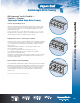
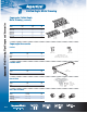
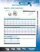
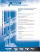
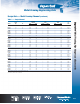
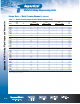
Table Of Contents

Metal Framing Engineering Data
Table 3
Beam Loads
Table 3 contains simple beam, uniformly-distributed loads calculated at 25,000 psi
fiber stress. Beam loads are based on channel being loaded across the x-x axis.
Loads are also listed at reduced deflections for long spans.
Maximum Loads @ 25,000 psi Stress
Maximum allowable deflections and maximum uniform loads for all spans
@ 25,000 psi fiber stress.
Reduced Load for all 1/180 Span Deflection
For moderate deflections on the longer spans, reduced loads are listed which will
produce a deflection equal to 1/180 of the span. When maximum loads do not induce
deflections exceeding 1/180 x the span length, reduced loads are not required.
Reduced Load for 1/360 Span Deflection
For very slight deflections on the longer spans, reduced loads are listed which will
produce a deflection equal to 1/360 of the span. When maximum loads do not induce
deflections exceeding 1/360 x the span length, reduced loads are not required.
Concentrated Loads
To obtain values for concentrated loads from Table 3, multiply uniform load
by 0.5 and deflection by 1.25.
Slotted, Punched or KO Channel
Reduce load rating 5%.
Long Span Deep Beams
Support in a manner to prevent rotation at supports and tie between supports
to prevent twist.
Column Loads
Allowable column loads given are for uniform axial loading with pinned ends.
For eccentric loading or other end conditions, reduce allowable loads according
to standard engineering practice.
Dynamic Loads
Allowable dynamic loads may be calculated by dividing the static loads shown
in Table 3, by 2.08.
Design Data — Metal Framing Channel
(continued)
Design Loads for Channel Used as Beam or Column.
D-98
Metal Framing, Pipe Hangers and Accessories