
Cut Sheet
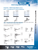
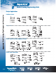


Table Of Contents

Metal Framing Engineering Data
D-111
Metal Framing, Pipe Hangers and Accessories
LOAD DEFLECTION
LOAD AND SUPPORT CONDITION FACTOR FACTOR
1. Simple Beam — Uniform Load 1.00 1.00
2. Simple Beam — Concentrated Load at Center .50 1.25
3. Simple Beam — Two Equal Concentrated Loads
at
1
⁄4 Points 1.00 1.10
4. Beam Fixed at Both Ends — Uniform Load 1.50 .30
5. Beam Fixed at Both Ends — Concentrated Load 1.00 .40
at Center
6. Cantilever Beam — Uniform Load .25 2.40
7. Cantilever Beam — Concentrated Load at End .12 3.20
8. Continuous Beam — Two Equal Spans — 1.30 .92
Uniform Load on One Span
9. Continuous Beam — Two Equal Spans 1.00 .42
10. Continuous Beam — Two Equal Spans — .62 .71
Concentrated Load at Center of One Span
11. Continuous Beam — Two Equal Spans — .67 .48
Concentrated Load at Center of Both Spans
Design Applications
(continued)
Load tables on page D-50–D-56 for A, B, C, E and H series channel are for single span beams supported at the ends. These can be used in the majority
of cases. There are times when it is necessary to know what happens with other loading and support conditions. Some common arrangements are shown
in Table 6. Simply multiply the loads from the Design Load Tables times the factors given in Table 6. Examples shown on page D-112.
Span Span
Table 6 — Conversion Factors for Beams with Various Static Loading Conditions