
User's Manual


REPLACING THE WIRE ROPE
Replace damaged wire rope with
the manufacturer’s recommended
replacement part or a factory
approved equivalent identical in
strength, quality, lay, and stranding.
Pass the attaching end of wire rope
through the fairlead and attach it
to the drum. When inserting the
wire rope into the drum, insert it
into the correct end of the hole
provided (See Figure 8). Tighten the
set screw securely.
It is important that the wire rope be
wound tightly onto the drum.
HANDLING THE WIRE ROPE
Use heavy
leather gloves
when handling wire rope. Do not
allow wire rope to slide through
hands.
1. Never winch with less than 5
turns of wire rope around winch
drum, since wire rope and fasten-
er may not withstand the load.
ALWAYS USE HANDSAVER BAR
WHEN GUIDING HOOK FOR THE
LAST FEW FEET OF ROPE
(See Figure 9)
Keep clear of
winch wire rope
and hook when operating winch.
Never put your finger through the-
hook. Placing finger(s) in hook
could result in injury.
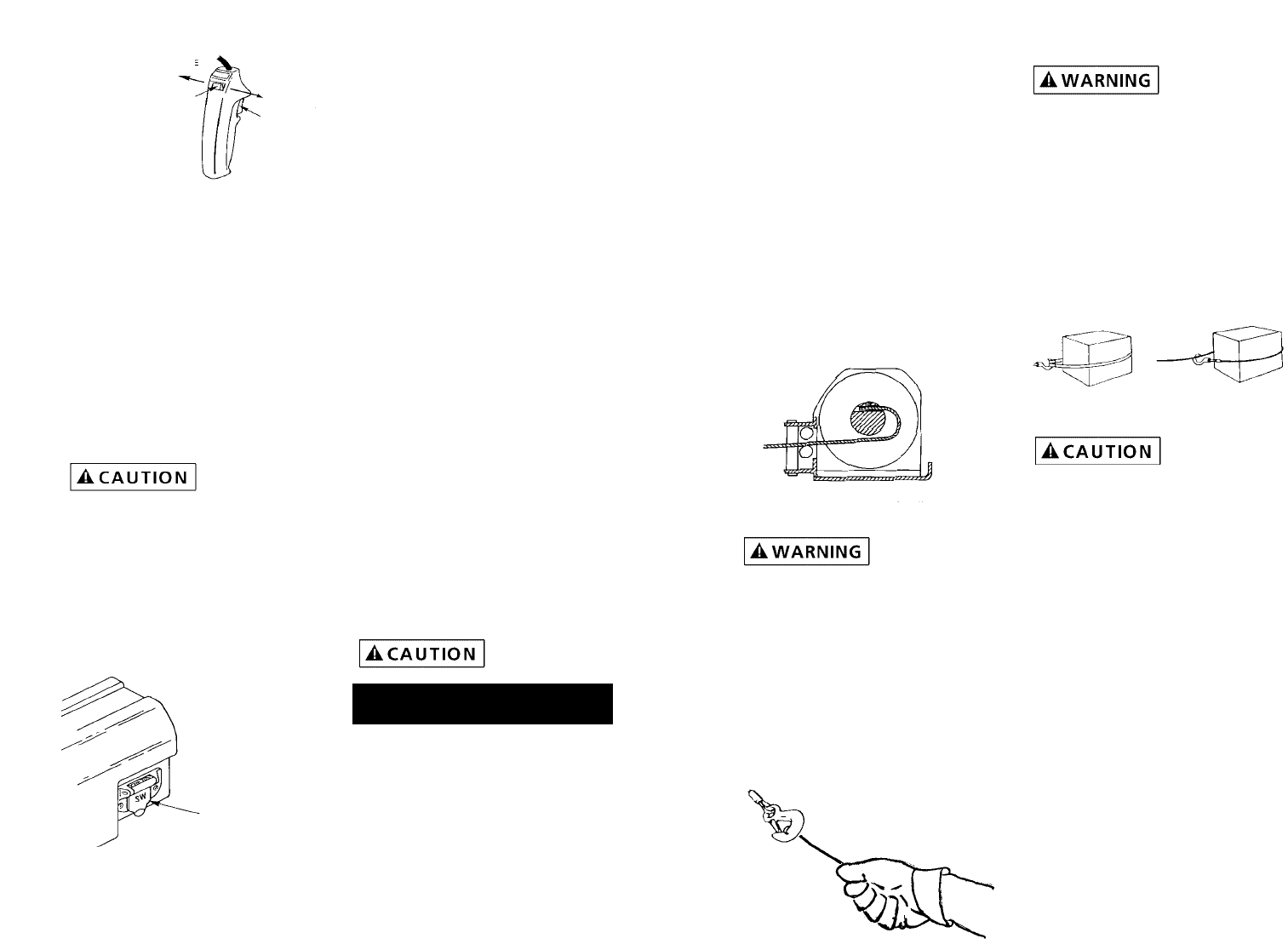
2. Never hook wire rope back onto
itself. Hooking wire rope onto
itself can damage rope. Use a
nylon sling (See Figure 10). When
using a sling, make sure that sling
is properly seated in saddle of
hook.
Avoid continu-
ous pulls from
extreme angles. This will cause wire
rope to pile up at one end of drum.
This can jam wire rope in winch
causing damage to rope or winch
itself.
3. Do not use wire rope as a ground
for welding.
4. Never touch welding electrode to
wire rope.
5. Keep wire rope tight and even on
drum.
6. Replace wire rope when frayed.
TIPS FOR EXTENDING THE LIFE OF
YOUR WINCH
1. Keep a tightly wound wire rope
drum. Do not allow the wire rope
to become loosely wound. A
loosely-wound drum allows a
wire rope under load to work its
way down into the layers of wire
rope on the drum. When this
happens, the wire rope may
become wedged within the body
of the windings, damaging the
10
11
PENDANT OPERATION
The switch trigger returns to the
“OFF” position when released (See
Figure 6, Ref. A). The slide button
on the back of the switch deter-
mines the direction of the drum
rotation for lowering or lifting a
load (See Figure 6, Ref. B). The slide
is fitted with an interlock so that
the motor cannot be reversed if the
trigger is depressed. To change
direction, release the trigger, move
the slide button, and depress the
trigger again.
The switch
assembly must
be kept free of dirt and moisture to
ensure safe operation.
To connect the pendant control, lift
the dust cover on the plug recep-
tacle (See Figure 7), and insert the
plug end of the remote switch. The
plug on the pendant control cord is
keyed and will fit into the socket
only one way.
Do not allow winch motor to over-
heat. The winch is for intermittent
use only. During long or heavy pulls
the motor will get hot. Allow to
cool after 2 minutes of “ON” time.
MAINTENANCE AND REPAIR
Periodically check tightness of
mounting bolts and electrical con-
nections. Remove any dirt or corro-
sion that may have accumulated on
the electrical connections.
BRAKE OPERATION
Your winch has a wrap spring brake
that stops and holds loads up to
1,000 lb. (454 kg). When the winch
is powered out, as in releasing a
load, the brake is engaged and the
motor must overpower the brake
resistance to rotate the drum.
Therefore, it is normal for the
winch to operate faster in one
direction than the other. The brake
is designed for the wire rope to be
used in the underwind position
only. Drum must turn counterclock-
wise, looking from motor end,
when winching in.
DO NOT
OVERWIND.
Powering against the
brake will cause heat to build up in
the drum and may transfer heat to
the wire rope. DO NOT POWER OUT
FOR MORE THAN 2 MINUTES.
The drum may
get very hot.
WIRE ROPE
For safety reasons, it is important
that you use a wire rope with a
break strength of at least 5,600 lbs.
Recommended wire rope for this
winch will have a 1/4" diameter
with a 7 x 19 construction, and a
minimum break strength of 7,000
lbs. or a 7/32" diameter with 7 x 19
construction, with a minimum break
strength of 5,600 lbs.
Figure 10
Right
Wrong
OPERATION
Figure 6
POWER
OUT
POWER
IN
A
B
Figure 7
DUST
COVER
Figure 8
Figure 9