OWNER’S MANUAL H8P-PRO / H10P-PRO EN 14492-1 HYDRAULICALLY POWERED WINCHES www.superwinch.com Winch shown for illustration purposes only Superwinch LTD. Superwinch LLC. Union Mine Road, Pitts Cleave Tavistock, Devon. PL19 0NS 359 Lake Road, Dayville CT06241 U.S.A. Tel: +44 (0) 1822 614101 Fax: +44 (0) 1822 615204 Tel: 01 800 323 2031 Fax: 01 860 963 0811 E-mail: sales@superwinch.net E-mail: info@superwinch.
Owner’s Manual 5050-PRO, H8P 5060-PRO, H8P 650006-PRO, H8P 5170-PRO, H10P 5172-PRO, H10P These instructions cover kits from 01/01/2010 01 INTRODUCTION 02 GENERAL SPECIFICATION DATA 03 INSTALLATION HYDRAULIC SYSTEM WINCH CABLE 04 MAINTENANCE AND USE FREESPOOL USE RUNNING IN, MAINTENANCE & SERVICING TIPS FOR EXTENDING THE LIFE OF YOUR WINCH 05 SPARES & ACCESSORIES 06 WARRANTY 07 NOTES For all your requirements please contact your Superwinch agent Owners Manual 5-201-001 Issue 3 Page 2 i
INTRODUCTION Thank you for purchasing a Superwinch Pro. It has been designed and manufactured to meet BS EN 14492-1, Power Driven Winches Standard, and provide years of trouble-free operation. Please read and understand this Owner’s handbook before using your winch. Your winch is a very powerful machine. If used unsafely or improperly, there is a possibility that property damage or personal injury can result.
02 SPECIFICATION DATA Gear Reduction: High efficiency planetary for optimum reliability. Drum: Fabricated steel mounted on maintenance free plain bearings. Braking: Full Load Holding. Mounting: Designed to most industry standard dimensions, this winch can be side, foot or angle mounted, flat bed or low mount. Pneu. Freespool Supply Pressure: 5.5 bar. Load Limiter: Hydraulic system relief valve on vehicle (installers responsibility).
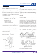
WINCH INSTALLATION 03 HYDRAULIC SYSTEM INSTALLATION System Type: Open system with filtered return line As a general rule: Bigger Nominal Bore Hose = Better Winch Performance Relief Valve: IMPORTANT - Set at winch operating pressure Pump: With a maximum oil supply of 60 l/min at top motor rpm. The pump must be capable of delivering a pressure of 170 bar. In all installation work on a hydraulic system, cleanliness and accuracy are essential so that the hydraulic system functions properly.
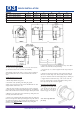
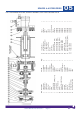
03 WINCH INSTALLATION VERSION H8P - 190mm DRUM LENGTH A B C D* E F* 207.0mm 190.0mm 602.0mm 228.5mm 298.5mm 311.0mm H8P - 253mm DRUM LENGTH 207.0mm 253.0mm 665.0mm 291.5mm 361.5mm 374.0mm H10P -190mm DRUM LENGTH 214.0mm 190.0mm 609.0mm 228.5mm 298.5mm 311.0mm H10P - 253mm DRUM LENGTH 207.0mm 253.0mm 665.0mm 291.5mm 361.5mm 374.0mm 6. Tighten the retaining screw ensuring that the rope end is flush with the exit of the hole and not protruding.
MAINTENANCE & USE 04 PNEUMATIC FREESPOOL OPERATION RUNNING IN, MAINTENANCE & SERVICING 1. Dis-engage the drum by operating the pneumatic control valve. For optimum performance all hydraulic motors need running in. Run for approximately 1 hour at 30% of maximum oil pressure. 2. Pull out the cable by hand, but leave at least 5 wraps on the drum. LUBRICATION 3. Attach the load. 4. Engage the drum by moving the control valve lever to the appropriate position.
04 MAINTENANCE & USE TIPS FOR EXTENDING THE LIFE OF YOUR WINCH 1. Note: Installing the wire rope is not included in the running-in period. Check tightness of all mounting bolts after running-in period. 2. Keep a tightly wound rope drum. Do not allow the windings on the drum to become loosely wound. A loosely wound spool allows a rope under load to work its way down into the layers of the wire rope on the drum.
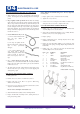
Owners Manual 5-201-001 Issue 3 Cap Hd Screw Screw Seal Roll Pin Spring Brake Housing Brake Housing, (5052Gg, only) Pressure Plate Friction Plate Assy Gasket Bearing Plate & Ball Bearing Ball Bearing Snap Ring Drive Shaft Sun Gear Thrust Washer 1st Stage Carrier Assy 2nd Stage Carrier Assy 3 4 5 6 7 7 8 9 10 11 12 13 14 15 16 17 19 Item Description 1 Cap Hd Screw 2 Spring Washer Page 9 10011 4-36-0601022 4-23-063 4-56-802003 4-31-1403030403 50-90622-01 50-25160 10002 10028 10063 50-95074 Part of 50-9
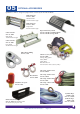
05 OPTIONAL ACCESSORIES Optional accessories, designed by Superwinch exclusively for the H8 and H10P: Roller Fairlead Part No. 5600 Standard Drum 190 mm Drum Length Roller Fairlead Part No. 5610 Long Drum 253 mm Drum Length Rope Drum Safety Guard Part No. 50-30171, Standard Drum Part No. 50-30172, Long Drum Cable Tensioner Part No. 5606 Short Drum 190 mm Drum Length Cable Tensioner Part No. 5607 Long Drum 253 mm Drum Length Pulley Block, 9000kg Part No. 7750 Winch accessory kit Part No.
SUPERWINCH LIMITED WARRANTY VALID WORLD WIDE 06 Limited Warranty. Superwinch (“seller”) warrants the original buyer (“you”) all parts and components except wire rope to be free from defects in materials and workmanship for a period of (one) 1 year from the provable date of purchase. Any Superwinch product which is defective will be repaired or replaced without charge to you, upon compliance with these procedures.
NOTES Owners Manual 5-201-001 Issue 3 Page 12 07