
User Manual

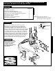

Hole pattern in switch box mounting bracket allows switch box mounting in any one of several
positions and orientations. Always use both box combination head mounting screws provided. Punch
out the appropriate two mounting holes in the switch box. Short and long extension links are provided
to elevate the switch as needed. Do not use more than one link to mount the switch box mounting
bracket to the round tube clamps.
ALWAYS USE THE BOX MOUNTING BRACKET, TWO SCREWS AND LOCK NUTS
PROVIDED. Screw lengths are sized for correct penetration into the switch box.
Excess penetration may result in short circuits that could lead to wire overheating.
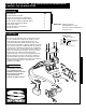
To help protect your switch, winch, and vehicle electrical systems, a new sealed Duty-Safe® breaker has
been included. This breaker replaces the metal can circuit breaker. Remove and discard the old metal
can circuit breaker. Connect the smaller ring terminal on short red wire supplied in this kit to the +BAT
terminal of the duty safe breaker. Connect the red wire from the switch removed from the old circuit
breaker to the unmarked terminal on the duty safe breaker.
Two terminal boots are supplied with this kit to insulate the terminals on the duty safe breaker. After
installing the boots over the wires, the boots can be secured to a non-metal part on the vehicle to hold
the duty safe breaker in place. Insulated clips, wire ties or tape may be used.
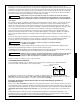
Connect the black wire from the battery to switch terminal #4. Connect the black or yellow wire from
the motor to switch terminal #1. Connect the red or blue wire from the motor to switch terminal #3.
Connect the red wire from the unmarked terminal of the duty safe breaker to switch terminal #2.
Be sure that wires do not come into contact with hot or
sharp surfaces on the vehicle.
Insert each wire into the loom slots on the back of the switch box. Fasten the top lid of the switch box
using the supplied self-tapping screws.
Two pieces of split loom tubing are provided. Bundle the two wires to the motor in one piece of tubing
and the two wires to the battery in the other piece of tubing.
Be sure the switch mounting position does not impede the operation of the vehicle.
Before driving the vehicle, test the vehicle control system range of motion to ensure
that switch wiring does not interfere with vehicle operation.
Reconnect the red and black leads to the battery.
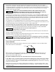
SWITCH OPERATION
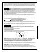
With the switch installed as described in the previous section, the legend on the rocker will indicate
winch drum rotation as shown below.
When the switch is depressed in either direction, the winch activates. “ROPE IN” winds wire rope
onto the winch drum. “ROPE OUT” powers wire rope off of the drum. The switch automatically
returns to the neutral “OFF” position.
The switch assembly must be kept free of dirt and moisture to ensure safe operation.
In the “OFF” position, an electrical shunt provides dynamic braking action, which reduces the possibility
of the winch coasting. Thus shunt reduces the action of a load backdriving the winch. However, a load
can cause the winch to creep. Do not use the winch to hold loads in place. Use other means of securing
loads such as tie down straps.
Always disconnect winch power leads to battery before working in or around the winch drum so that
the winch cannot be turned on accidentally. A Quickconnect (Part No. 1551) is available as an accessory
to disarm the winch.
Superwinch Inc., Winch Drive, Putnam, CT 06260 • 860-928-7787 • FAX: 860-963-0811
ROPE OUT
ROPE IN
CAUTION
!
WARNING
!
WARNING
!