
Manual


9
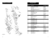
29. Always operate your winch in an
underwound orientation only.
MOUNTING YOUR WINCH
Superwinch mounting (fitting) kits are
available for most popular vehicles. If
you can‘t locate a kit locally, contact
Superwinch at the address listed on
the front of this manual for the name
of a Superwinch dealer near you.
Detailed mounting instructions are
provided with each mounting kit.
Read and install carefully to ensure
proper winch alignment and trouble-
free operation.
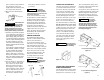
If a Superwinch mounting plate is not
used, refer to Figure 7 for a guide to
construct a mounting system.
Note: The winch can be mounted
foot down or foot forward. See page
11 for details. The preferred mount-
ing position is feet forward. This
winch MUST be mounted with the
wire rope in the underwind direction.
Improper
mounting could
damage your winch, void the
warranty, and cause personal
injury.
MINIMUM ELECTRICAL
REQUIREMENTS
For 12 Volt winches, a 60 amp alter-
nator and battery with 440 cold-
cranking amperes capacity are the
minimum recommended power
sources. If the winch is in heavy use,
an auxiliary battery and heavy duty
alternator with battery isolator are
recommended.
TOOLS REQUIRED
Open End Wrenches (Spanners):
*(2) 3/8", *(2) 1/2", *(2) 7/16",
*(2) 9/16"
(1) 1/4 inch Hex socket wrench or
straight blade screwdriver
*Adjustable (Crescent) Wrenches may be substituted.
1. Install mounting kit or structural
support for winch.
2. Change the foot orientation (if
required) see page 11.
3. Attach the long black color coded
wire and the ground wire from
solenoid pack to the motor case.
Mount the winch to the mount-
ing kit base plate or to the
mount that you designed (see
Figure 7).
The 3/8-16 mounting bolts sup-
plied are the correct length for
use with a 1/4" thick Superwinch
mounting plate.
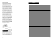
The end of the
mounting bolts
must not contact the opposite side
of the support casting’s mounting
pocket (see Figure 8).
Such contact could lead to a damaged
casting, catastrophic failure of the
winch and void the warranty. Adjust
bolt length accordingly if a thicker
plate is used. The bolt threads must
engage all the nut threads.
Always place the square nuts (pro-
vided) in the casting pockets when
mounting your winch.
Do not sub-
stitute any
strength grade weaker than SAE
Grade 8 (ISO 10.9). Grade marking
is found on the bolt head and is
pictured in Figure 8.
4. Mount the solenoid pack to the
solenoid pack bracket with the
1/4-20 bolts provided (see Figure
22). Do not mount the bracket to
the mounting plate at this time.
5. Recheck all wire connections that
you just made to be sure they are
correct. If you are using a
Superwinch mounting plate, bolt
the solenoid bracket to the
mount plate with the bolts, exter-
nal tooth lock washers, and nuts
provided.
Note: If a Superwinch
mounting plate is not used, the
solenoid pack must be mounted
in a way that will provide an elec-
trical ground path from the sole-
noid case to the battery negative
terminal. Without this ground
path the winch will not work.
If you choose to relocate the sole-
noid pack or the winch at a
greater distance than wires pro-
vided will permit, it may be nec-
essary to purchase a larger gauge
INSTALLATION
8
Support Casting
Mounting Pocket
Square Nut
Flat Washer
Lock Washer
(Must not
touch)
Grade 8 Bolt
Mounting
Plate
10.9
Figure 8
Figure 7
CAUTION
!
WARNING
!
NOTES:
1. All dimensions are in inches
(millimeters).
2. Winch is mounted with 3/8-16
(M 10) hardware. Using 1/4
inch (6.4) thick steel baseplate,
bolt length to be 1 inch (25.4).
Bolts to be SAE Grade 8
(ISO 10.9) or stronger.
3. Use only square nuts in casting
for mounting. (See Figure 8.)
MOUNTING DIMENSIONS
10 (254.0)
4 1/2
(114.3)
1 13/32 (35.7)
13/32 (10.3)
Dia. Holes
(4) Places
Alternate Construction of
Structural Reinforcement
Weld
4 1/8 (104.8)
7 1/2 (190.5)
1/4 (6.4)
1 3/8 (34.9)
1/2 (12.7)
Max. Rad.
1 9/16 (39.7)
5/32 (4.0)
19/32
(15.1)
7/8
(22.2)
13/32 (10.3) Dia.
10 5/16 (261.9)
3/16 (4.8)
Opening
1 3/16 (30.2)
9 (228.6) Opening
Fig. 2
Overwind
Underwind
WARNING
!