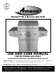
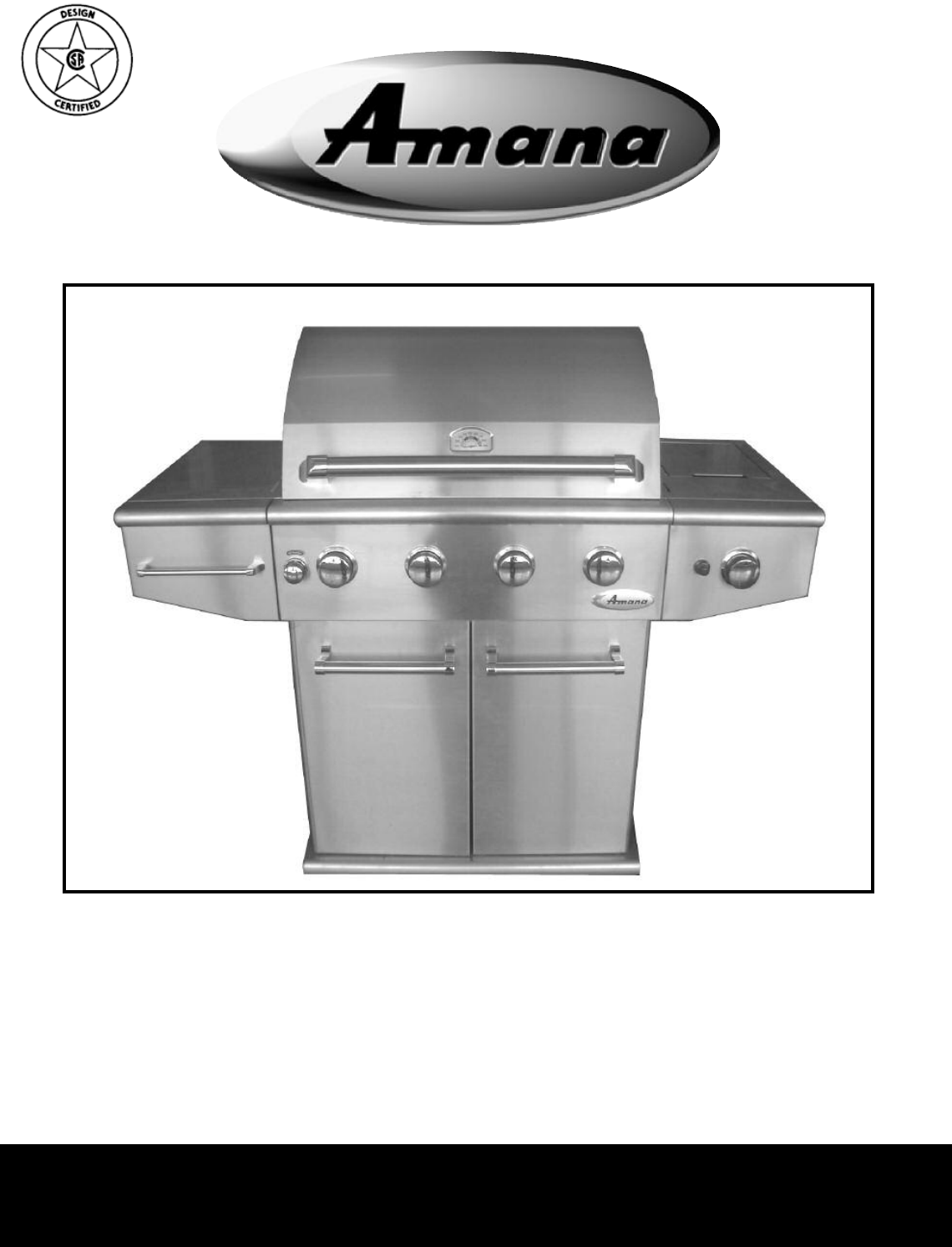
Amana™ SS 4 Burner Gas Grill USE AND CARE MANUAL FOR OUTDOOR USE ONLY ALWAYS KEEP YOUR GRILL COVERED WHEN NOT IN USE BEFORE YOU BEGIN – We’ ve included easy-to-follow, step-by-step instructions which have been carefully written to ensure quick assembly of your grill. Reading the instructions will be a time saver in the end. YOU WILL NEED – A Phillips screwdriver, adjustable wrench, 1/2” wrench or socket and a 1/4” nut driver or socket will be needed to assemble this grill.
IMPORTANT SAFETY INFORMATION - Read this manual carefully before using your grill to reduce the risk of fire, burn hazard or other injury. - Extreme care should be used because of the high temperatures produced by this appliance. CHILDREN SHOULD NOT BE LEFT UNATTENDED IN AN AREA WHERE THE GRILL IS BEING OPERATED. - This appliance must be kept clear from combustible materials, gasoline or other flammable vapors and liquids.
Welcome & Congratulations Questions? Congratulations on your purchase of a new grill! We are very proud of our product and we are completely committed to providing you with the best service possible. Your satisfaction is our #1 priority. 1-800-229-5647 for written inquiries: Sure Heat Manufacturing 3130 Moon Station Rd Kennesaw, GA 30144 Please read this Use & Care Manual very carefully. It contains valuable information on how to properly maintain your new grill.
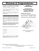
General Safety Instructions Do not use the rotisserie in the rain. NOTE: Do Not operate the main burners and infrared back burner at the same time. This can cause warping of the roll top grill hood. Electrical Grounding Instructions This appliance (rotisserie motor) is equipped with a three-prong (grounding) plug for your protection against shock hazard and should be plugged directly into a properly grounded three-prong receptacle. Do not cut or remove the grounding prong from this plug.
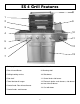
SS 4 Grill Features 1 8 2 9 4 10 3 11 5 12 6 13 7 1. Roll top grill hood 8. Hood Handle 3. Grilling/cooking surface 10. Side burner 2. Rear Infrared Burner 9. Warming shelf 4. Side shelf 11. Control knob: side burner 5. Towel bar/utensil hanger 12. Electronic igniter: main burners, side burner and rear infrared burner 6. Control knob: Rear infrared burner 13. Cart with doors 7.
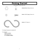
Getting Started All hardware is shown actual size.
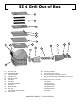
SS 4 Grill Out of Box 2a 12b 2c 5a 5b 12c 1a 3e 11b 2e 7 12a 11a 6 1b 1c 4a 2a. 12b. 2c. 5a. 5b 2e. 1a. 12c. 3e.
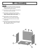
STEP ONE SS 4 Assembly a. Set the cart base on the floor and then lay the left wheel channel on the left and the right wheel channel on the right side of the cart base. b. Pick up the left side of the cart base and set the fixed wheel channel in place by inserting the attached bolts through the three (3) holes in the cart bottom. c. Pick up the right side of the cart base and set the swivel wheel channel in place by inserting the attached bolts through the three (3) holes in the cart bottom.
STEP TWO SS 4 Assembly a. Place the left cart side onto the two (2) outer fixed wheel channel bolts, make sure the large flange is toward the front of the cart base. b. Secure the left cart side in place by hand tightening nuts onto the wheel channel bolts. c. Place the right cart side onto the two (2) outer swivel wheel channel bolts, make sure the large flange is toward the front of the cart base. d. Secure the right cart side in place by hand tightening nuts onto the wheel channel bolts. e.
SS 4 Assembly STEP THREE a. Press the sides back together making sure that the side flanges cover the cart back flange. b. Attach three (3) self tapping screws through the pre-drilled holes on the left cart side into the cart back. Repeat for right cart side. c. Fasten two (2) nuts onto the back wheel channel bolts. The Spare L.P. Gas Tank Barrier must be installed to prevent storage of spare L.P. Gas Tanks.
STEP FOUR SS 4 Assembly a. Loosen the four (4) grill mounting bolts so that there is approximately 1/4” between the bolt head and grill bottom. b. Have someone help you pick up the grill and set it squarely on top of the cart. c. Make sure the four (4) bolts fall through the large opening on the “ key hole” slots on the sides of the cart. d. Slide the grill forward in the “ key hole” slots until the front grill flange rests against the side cart flanges.
SS 4 Assembly STEP FIVE right right a. Place left hand door on an angle over the left side door pivot. b. Tilt the top of the door toward the grill, while depressing the top door pivot pin. c. Move the door slightly until the pin locks into place in the hole at the bottom of the front face. left d. Repeat steps 5a - 5c for right door installation. e. The levels of the doors may be adjusted using the nuts on the pivot points.
STEP SIX SS 4 Assembly a. Lay the left shelf on its side with the shelf hooks facing up. With a Phillips head screwdriver, remove screw from handle end, and then attach one of the handle ends to the front of the shelf using the supplied phillips head screw. Note: Be careful not to scratch the side of the shelf. b. Before you slide the towel bar into place, be sure to slide the "S" hooks over the bar. Then slide one end of the bar into the installed handle end.
STEP SEVEN SS 4 Assembly a. On the inside bottom of the side burner assembly you will find the brass burner cap attached with tape. Remove and set aside. b. Feed the side burner gas supply hose assembly and two igniter wires through the grommeted hole in the side of the cart. c. Place a piece of styrofoam from the packaging in the grill to leave the grill hood propped open slightly. d. Attach the right side burner shelf by inserting the four shelf hooks into the slots on the side of the grill. e.
SS 4 Assembly STEP EIGHT a. Remove two screws from the burner valve assembly. b. Carefully insert the valve assembly into the cast burner. You will need to angle the tube into the burner assembly. Make certain that the hose is pointing down when the valve is put in place. Then push the valve stem out through the opening in the front of the side burner shelf assembly, lining up the holes on the valve assembly with the openings on the burner shelf. c.
SS 4 Assembly STEP NINE a. Place the electronic igniter into the igniter hole on the front left of the side burner shelf. To help ease the installation of the wires, make certain that the igniter wire tabs are facing outwards from the grill. b. Secure the igniter in place using the plastic lock nut. Make sure to tighten securely. c. Install AA battery, negative side first. Close-up of igniter wires attaching to igniter. d. Install spring and cap assembly and tighten securely. e.
STEP TEN SS 4 Assembly a. Center the brass burner cap on top of the side burner head. b. Place the side burner grate on to the side burner tray.
STEP ELEVEN SS 4 Assembly a. Slide the condiment basket into the slots located inside of the left hand cart door. b. Slide drip tray in place.
STEP TWELVE SS 4 Assembly a. Insert the top row of flavor grids into the cutouts with triangle ridges facing up. b. Install cooking grates on the ledges provided on the grill to create your cooking surface. c. Rest warming shelf on four (4) slots above cooking grid. The finished grill should look like the photo on the cover of this Use and Care Manual. Clean the outside of the grill using only a soft cloth and non-abrasive soap and water or approved stainless steel cleaner.
Gas Requirements GENERAL INFORMATION Never attach an unregulated gas line to the appliance. Connection to an unregulated gas line can cause excessive heat or fire. Verify the type of gas supply to be used, either Natural Gas (N.G.) or Liquid Propane (L.P.), and make sure the serial plate agrees with that of the supply. Conversion kits are available separately for an additional cost which will enable you to convert your grill from L.P. to N.G. or to convert your grill from N.G. to L.P.
Gas Requirements L.P. GAS INSTALLATION Amana™Gas Grills that are set to operate with L.P. gas come with a high capacity hose and regulator assembly. (Note: Only use the pressure regulator and hose assembly supplied with the grill or a replacement pressure regulator and hose assemblies specified by Amana™). This assembly is designed to connect directly to a standard 20 lb. L.P. cylinder. L.P. Cylinders are not included with the grill. L.P. Cylinders can be purchased separately at an independent dealer.
Pre Operation Leak Testing GENERAL INFORMATION Although all internal gas connections on the grill are leak tested prior to shipment, a complete gas tightness check must be performed at the installation site due to possible shifting during shipment, installation or excessive pressure unknowingly being applied to the unit. Periodically check the whole system for leaks and immediately check the system if the smell of gas is detected. BEFORE TESTING Do not smoke while leak testing.
BEFORE LIGHTING Lighting the Grill burner between the flavor grids. Position the match near the burner ports and push and turn the control knob counter clockwise to the “ HIGH” position. (See Fig. 50-51) Important! Before Lighting: • Check the gas supply line for cuts, wear or abrasion. Note: If the grill will not light after several attempts see the trouble-shooting section of this manual. Turn the control knobs to the OFF position when not in use.
GRILL LOCATION Using the Grill Do not use the grill in garages, breezeways, sheds or any enclosed area. Never operate the grill in enclosed areas as this could lead to a carbon monoxide buildup, which could result in injury or death. Place the grill on a level surface. Avoid moving the grill while it is operation. NOTE: The grill will operate best if it is not facing directly into the wind.
Accessory Lighting ROTISSERIE LIGHTING Open the lid. Push and turn the control knob for the rotisserie counter clockwise to the “ HIGH” position. Wait 5 seconds. Then press and hold the electronic igniter button. You’ ll hear a snapping sound. If the burner does not light in 4 seconds, turn the control knob to OFF and wait 5 minutes before trying again. Once lit, turn the control knob to the desired setting. (See Fig.
SS 4 Replacement Parts Sheet 12 1 2 7 3 4 5 15 8 9 19 13 14 6 20 21 22 23 16 24 26 11 10 NS* NS* NS* NS* NS* NS* NS* NS* 1. 2. 3. 4. 5. 6. 7. 8a. 8b. 9. 10. 11. 18 25 27 28 17 Bag of 13 Self-Tapping Screws Bag of 6 Wheel Channel Nuts Set of 3 “ S” Hooks (See Fig. 24) Match Extender Condiment Basket (See Fig.
SS 4 Replacement Parts Sheet 45 31 32 35 38 40 31. 32. 33. 34. 35. 36. 37. 38. 39. 40. 41. 42. 43. 44. 45. 46. 47. 48. 49. 50. 51. 52. 53. 46 33 50 73 47 34 49 36 64 48 62 54 44 39 42 56 63 61 72 54. 55. 56. 57. 58. 59. 60. 61. 62. 63. 64. 65a. 65b. 65c. 66. 67. 68. 69. 70. 71. 72. 73.
DRIP TRAY Care and Maintenance The drip tray located below the grill, inside the cart, should be cleaned periodically to prevent heavy buildup of debris. Note: Allow the drip tray to cool before attempting to clean. Important: Do not leave the grill outside during inclement weather unless it is covered (cover sold separately). Rain water can collect inside of the grill, the grill cart or the drip tray if left uncovered.
PROBLEM Troubleshooting Your Grill SOLUTION Grill will not light with a match or low heat with dial set to "High" position. • Is your gas supply fully turned on? • If this is an L.P. grill is there gas in your tank ? Check your gas level. • If this is an L.P. grill, shut off gas supply, disconnect gas line at tank, reconnect the line to the tank. • Make sure all the knobs are in the off position, then open the gas supply valve on the L.P.
Warranty LIMITED WARRANTY Sure Heat Mfg warrants that for the lifetime of the product from the date of purchase, the stainless steel panels will not break due to defects in material or workmanship, and that for a period of four years from the date of purchase, the stainless steel burners will be free from defects in material and workmanship. All other components of this barbecue grill are warranted free from defects in material and workmanship for one year from the date of purchase.