AMANA® THREE BURNER GAS GRILL Assembly/Installation Instructions and Use & Care Guide AM27LP DPCI 009 07 0291 FOR OUTDOOR USE ONLY For questions about features, operation/performance, parts, accessories or service, call: 1-800-229-5647 or visit our website at www.sureheat.com IMPORTANT: Save for local inspector's use. Installer: Leave installation instructions with the homeowner. Homeowner: Keep installation instructions for future reference.
TABLE OF CONTENTS OUTDOOR GRILL SAFETY............................................................................................................3-4 UNPACKING INSTRUCTIONS...........................................................................................................5 ASSEMBLY REQUIREMENTS.......................................................................................................5-6 Parts Supplied........................................................................................
OUTDOOR GRILL SAFETY Your safety and the safety of others are very important. We have provided many important safety messages in this manual and on your appliance. Always read and obey all safety messages. This is the safety alert symbol. This symbol alerts you to potential hazards that can kill or hurt you and others. All safety messages will follow the safety alert symbol and either the word “DANGER” or “WARNING.
IMPORTANT: This grill is manufactured for outdoor use only. For grills that are to be used at elevations above 2000 ft (609.6 m) orifice conversion is required. See “Gas Supply Requirements” section. It is the responsibility of the installer to comply with the minimum installation clearances specified on the model/serial rating plate. The model/serial rating plate for freestanding models can be found on inside of the right cart door.
UNPACKING INSTRUCTIONS 1. Using a utility knife, cut the tape to open top flaps of carton. 2. Remove Assembly/Installation Instructions and Use and Care Guide. 3. Remove the large cardboard panels on the top and each side of the inside of the carton. 4. Remove the cart base on the top of the inside of the carton. 5. Remove the cart side panels located at the side the grill head assembly. D B 6. Using a utility knife, vertically cut at the side corners of the carton, lay the box sides flat. 7.
ASSEMBLY REQUIREMENTS Assembly Hardware Supplied ■ 20 - self-tapping screws ■ 2 - sunken head self-tapping screws ■ 8 - M6 x 40 Phillips pan head screws ■ 1 - Side burner knob with bezel ■ 1 - “AA” battery NOTE: Other hardware required is attached to the grill where needed.
ASSEMBLED GRILL VIEW E D C B F G I A H J A. Control knob: main burners G. Side burner C. Grilling/cooking surface I. Electronic igniter: main burners and side burner B. Side shelf D. Roll top grill hood E. Hood handle F. Bread warming rack H. Control knob: side burner J.
ASSEMBLY INSTRUCTIONS Step 1: Assemble Grill Cart Base C A B A. Cart base B. Cylinder limit handle C. Self tapping screw 1. Use two (2) self-tapping screws to secure the cylinder limit handle on the cart base as shown.
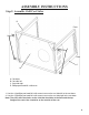
ASSEMBLY INSTRUCTIONS Step 2: Assemble Grill Cart Sides B Front D D Rear A C A. Cart base B. Cart side left C. Cart side right D. Phillips pan head M6 x 40 screw 1. Use four (4) phillips pan head M6 x 40 scews to secure the cart side left to the cart base. 2. Use four (4) phillips pan head M6 x 40 scews to secure the cart side right to the cart base. Note: The poles have two holes on the side that should be at the front and the top flange of the cart sides should be on the outside of the cart.
ASSEMBLY INSTRUCTIONS Step 3: Assemble Casters A Left B Right C D A. Cart side left B. Cart side right C. 3” Swivel casters D. 3” Swivel casters with brake 1. Hand screw the two swivel casters to the cart side left, then use the supplied wrench to tighten the two swivel casters to the cart side left as shown. 2. Hand screw the two swivel casters with brake to the cart side, then use the supplied wrench to tighten the two swilvel casters with brake to the cart side right as shown.
ASSEMBLY INSTRUCTIONS Step 4: Assemble Grill Cart back A B Front C Rear A. Cart back B. Self-tapping screws C. Tank secure ring 1. Use four (4) self-tapping screws to secure the grill cart back to the rear of the cart sides as shown. 2. Install the tank secure ring to the cart back.
ASSEMBLY INSTRUCTIONS Step 5: Assemble Cart Front Top Bar B D A D C A. Cart front top bar B. Self-tapping screws C. Sunken head self tapping screws D. Cart door pivot bracket 1. Use four (4) self-tapping screws to secure the cart front top bar onto the cart sides. 2. Use two (2) sunk head screws to secure the cart door pivot brackets in position.
ASSEMBLY INSTRUCTIONS Step 6: Assemble Grill Cart Door D D E A B C A. Grill cart door right B. Grill cart door pivot C. Grill cart door pin D. Grill cart door pivot bracket E. Cart door Left 1. Remove the two screws on the door hanle and use them to install the handle on the cart door left. 2. Repeat step 1 to install the handle on the cart door right. 3. Place cart door right on an angle over the right side door pivot. 4.
ASSEMBLY INSTRUCTIONS Step 7: Assemble Grill Head Assembly A B B A. Grill head assembly B. Self-tapping Screws 1. Remove the side burner valve/regulator hose assembly from underneath the control panel. 2. Have someone help you pick up the grill head assembly and set it on top of the cart as shown. 2. Use six (6) M5 x 12 Phillips Pan Head Screws to secure the grill head assembly on the top of the cart sides.
ASSEMBLY INSTRUCTIONS Step 8: Assemble Side Shelf Left A B C A. Side shelf left assembly B. 5/16-24 Hex Head screws C. self-tapping screw C 1. Loosen the four (4) 5/16-24 Hex Head screws on the left side of the grill as shown. 2. Attach the left side shelf by inserting the four (4) screws on the side of the grill head into the four (4) key hole slots on the left shelf. 3. Tighten the four (4) screws with a wrench. 4. Install one (1) self-tapping screw into the bottom front slotted hole of the shelf.
ASSEMBLY INSTRUCTIONS Step 9: Assemble Side Burner Shelf Right B A C A. Side burner shelf right assembly B. 5/16-24 hex head screws C. Self-tapping screw C 1. Remove the brass burner cap attached with tape along with side burner grate and set aside. 2. Loosen the four (4) 5/16-24 hex head screws. 3. Attach the side burner shelf by inserting the four (4) screws on the side of the grill head into the four (4) key hole slots on the side burner shelf. 4.
ASSEMBLY INSTRUCTIONS Step 10: Assemble the Side Valve C B D A A. Side burner valve assembly B. Large bezel C. Phillips pan head screw D. Control knob 1. Using a Phillips screwdriver, remove the 2 screws from the side burner valve assembly. 2. Push the valve stem out through the opening in the front of the side burner shelf, lining up the threaded holes in the side burner valve assembly with the openings on the side burner shelf. 3.
ASSEMBLY INSTRUCTIONS Step 11: Assemble the Side Burner Casting B A B A A. Side burner casting B. Side burner valve orifice 1. Remove the two phillips pan head screws from the side burner casting. 2. Angle the side burner casting and insert it into the center hole on the side burner tray. 3. Slide the side burner casting back in position to get the side burner valve orifice into the side burner casting.
ASSEMBLY INSTRUCTIONS Step 12: Assemble the Side Burner Bracket C B A A. Phillips pan head screw B. Small bracket C. Self tapping screws 1. Use the two (2) screws removed in step 1 on page 18 to secure the head of side burner casting on the rear bracket. 2. Use the two (2) self-tapping screws to attach the small bracket to the front bracket under the side burner tray.
ASSEMBLY INSTRUCTIONS Step 13: Assemble Igniter Module B A C E D A. Igniter module B. Side burner igniter wire C. Main burner igniter wires D. Igniter push button E. “AA” size battery 1. Unscrew the igniter button cap from the igniter module. 2. Install battery into battery compartment, negative (-) end in first. 3. Screw igniter push button cap on. 4. Connect loose igniter wires from the grill to the open terminals of the igniter.
ASSEMBLY INSTRUCTIONS Step 14: Assemble the Side Burner Accessories B A A. Brass burner cap B. Side burner grate 1. Center the brass burner cap on top of the side burner head. 2. Place the side burner grate onto the side burner tray. Position the 3 longer legs of the grate into the holes around the side burner.
ASSEMBLY INSTRUCTIONS Step 15: Assemble the Drip Pan B A A. Drip pan B. Drip pan holder 1. Place the drip pan holder on the grill head bottom. 2. Place the drip pan into the drip pan holder.
ASSEMBLY INSTRUCTIONS Step 16: Complete the grill assembly C B A A. Flavor grids B. Main cooking grates C. Bread warming rack 1. Insert the flavor grids into the cutouts with triangle ridges facing up. 2. Install main cooking grates on the ledges provided on the grill to create the cooking surface. 3. Rest bread warming rack on the two brackets through the cutouts on the hood support sides.
INSTALLATION REQUIREMENTS Location Requirements 24 ” 24” Select a location that provides minimum exposure to wind and traffic paths. The location should be away from strong draft areas. Do not obstruct flow of combustion and ventilation air. Clearance to combustible construction: ■ A minimum of 24” (61 cm) from grill hood sides and grill back must be maintained from any combustible construction.
INSTALLATION REQUIREMENTS Product Dimensions 27” (68.8cm) 13.125” (33.4cm) 53.625” (136.3cm) 45” (114.4cm) 33.875” (86.1cm) 21” (53.3cm) 20.875” (53.0cm) Gas Supply Requirements A A. Model/serial number plate Observe all governing codes and ordinances. IMPORTANT: This installation must conform with all local codes and ordinances. In the absence of local codes, installation must conform with American National Standards Institute, National Fuel Gas Code ANSI Z223.1 latest edition or CAN/CGA B149.
INSTALLATION REQUIREMENTS Gas Supply Line Pressure Testing Testing above ½ psi (3.5 kPa) or 14" (35.5 cm) WCP (gauge): The grill and its individual shutoff valve must be disconnected from the gas supply piping system during any pressure testing of that system at test pressures greater than ½ psig (3.5 kPa). Testing below ½ psi (3.5 kPa) or 14" (35.
INSTALLATION INSTRUCTIONS Check the burners The burners are tested and factory-set for most efficient operation. However, variations in gas supply and other conditions may make minor adjustments to air shutter or low flame setting necessary. It is recommended that a qualified person make burner adjustments. Checking the grill burner flames requires removing the grate and flavor grids.
OUTDOOR GRILL USE Control Panel OFF OFF M L A L B A. Left burner control knob B. Middle burner control knob C. Right burner control knob Using Your Outdoor Grill H M H M L C D. Igniter button E. Side burner control knob D Inspect the LP Gas Fuel Cylinder Supply Hose Inspect the gas pressure regulator/hose assembly before each use. 1. Inspect the gas pressure regulator/hose assembly for cuts, abrasions, or excessive wear. 2.
OUTDOOR GRILL USE Using Your Outdoor Grill (cont.) Manually Lighting Grill 1. Do not lean over the grill. 2. Remove the manual lighting extension and attach a match to the split ring. 3. Strike the match to light it. 4. Guide the lit match between the grill grate and one of the slots in the flavor grid. 5. Push in and turn the main burner knob to HIGH. The burner will light immediately. When burner is lit, turn knob to desired setting. 6. Remove match and replace manual lighting extension.
TIPS FOR OUTDOOR GRILLING Before Grilling ■ Thaw food items before grilling. ■ Lightly oil the grill grates or the food when cooking low-fat cuts of meat, fish or poultry, such as lean hamburger patties, shrimp or skinless chicken breasts. ■ Using too much oil can cause gray ash to deposit on food. ■ Trim excess fat from meats prior to cooking to reduce flare-ups. ■ Make vertical cuts at 2" (5 cm) intervals around the fat edge of meat to avoid curling.
OUTDOOR GRILL CARE Replacing the Igniter Battery If igniters stop sparking, the battery should be replaced. 1. Unscrew igniter button cap counter clockwise to remove. 2. Remove battery from the battery compartment. 3. Replace with a new alkaline “AA” size battery. Install battery with negative end in first. 4. Screw igniter push button cap clockwise into place. General Cleaning B A A. Igniter push button B.
OUTDOOR GRILL CARE (cont.) General Cleaning (cont.) WARMING SHELF Cleaning Method: ■ Liquid detergent or an all-purpose cleaner. ■ Rinse with clean water and dry with soft, lint-free cloth. ■ For tough spots or baked-on grease, use a commercial degreaser designed for stainless steel. EXTERIOR IMPORTANT: Make sure gas supply is off and all control knobs are in the OFF position. Make sure the side burner is cool.
OUTDOOR GRILL CARE (cont.) General Cleaning (cont.) DRIP PAN AND SHELF IMPORTANT: The drip pan should only be removed when grill is completely cool. The drip pan collects grease that runs out through the grill. Clean often to avoid grease buildup. The drip pan shelf collects grease and food particles that fall through the grill. Cleaning Method: ■ Remove drip pan. Wipe excess grease with paper towels. ■ Clean with mild detergent and warm water. Rinse and dry thoroughly.
Grill will not light TROUBLE SHOOTING ■ Is the 20 lb LP gas fuel cylinder valve turned off? Turn the 20 lb LP gas fuel cylinder on. ■ Is the grill properly connected to the gas supply? Contact a trained repair specialist or see Installation Instructions. ■ Is there gas in the 20 lb LP gas fuel cylinder? Check the gas level. ■ Is the igniter working? Check that the igniter battery is properly installed or check to see if the battery needs to be replaced. See the “Replacing the Igniter Battery” section.
REPLACEMENT PARTS Hood Assembly Front Face Overlay 1 set 1 set FCTG2708001 FCTG2708005 Hood Handle Amana Logo 1 pcs 1 pcs FCTG2608002 FCTG2608008 Temp Guage Front Face Heat Shield 1 pcs 1 pcs FCCS0007030 FCTG2708006 Hood Support Assy. Manifold & Valve Assy. 1 set 1 pcs FCTG2708002 FCTG2608010 Bread Warmer Rack Main Cooking Grates (3 pcs) 1 pcs 1 set FCTG2708003 FCTG2708007 Regulator & Hose Assy. Flavor Grid (3 pcs) 1 pcs 1 set FCTG2608005 FCTG2608012 Front Face Assy.
REPLACEMENT PARTS Front top cross bar Cart side right 1 set 1 set FCTG2708017 Cart back Swivel Caster with Lock 1 set 2 pcs FCTG2708008 FCTG2608022 Cart door right assy. Swivel Caster 1 set 2 pcs FCTG2708009 FCTG2608023 Cartl door left assy.
REPLACEMENT PARTS Side Burner Right Assy.
LIMITED WARRANTY Sure Heat Mfg warrants that for 2 years from the date of purchase, the stainless steel panels will not break due to defects in material or workmanship. All other components of this grill are warranted free from defects in material and workmanship for one year from the date of purchase. Sure Heat Mfg. at its option, will repair or replace this product or any component of the product found to be defective during the warranty period.