Tri-Band Wireless Adjustable Signal Booster INTRODUCTION 2 PRINCIPLES OF OPERATION 2 SURECALL TRIFLEX PACKAGES 3 TRIFLEX BOOSTER HARDWARE 4 INSTALLATION 5 PACKAGE CONTENTS 5 SITE SELECTION 5 CONFIGURING GAIN SETTINGS 6 INSTALLATION INSTRUCTIONS 7 TROUBLESHOOTING 10 FREQUENTLY ASKED QUESTIONS 12 OBTAINING TECHNICAL SUPPORT 12 3G – 4G Home Signal Booster Kit TRIFLEX-T for T-Mobile 2G thru 4G WARRANTY 13 SPECIFICATIONS 15 SAFETY INFORMATION 16 (TRIFLEX-T) User Guide TRIFLEX-T HOME
INTRODUCTION Introduction Congratulations on purchasing the SureCall TriFlex - T kit for 2G-3G, all carriers, and 4G for T-Mobile, the finest cellular signal booster available! SureCall adjustable cellular boosters and kits remove the frustration over dropped calls, limited range, and slow data rates by amplifying incoming and outgoing cellular signals in residences and homes.
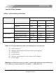
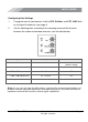
INTRODUCTION SureCall TriFlex Packages TriFlex - Antenna Kitting Information Component Prod No. (Description) Gain/Loss AWS-T Outdoor Antennas Outdoor Cable Indoor Cable Indoor Antenna 800 MHz 1900 MHz CM288W 3dBi 3dBi 4dBi CM230W 10dBi 10dBi 10dBi CM240-40FN (40 Feet) -3.52 dB -3.98 dB -6.52 dB CM400-75NN (75 Feet) -4.22 dB -4.41dB -6.17 dB CM240-20FN (20 Feet) -2.06 dB -2.29 dB -3.56 dB CM400-30NN (30 Feet) -2.05 dB -2.12 dB -2.
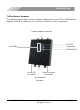
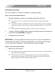
INTRODUCTION TriFlex Booster Hardware The following figure shows the key hardware components on the TriFlex 65dB cellular booster. Refer to this figure as you install your SureCall TriFlex components. Outdoor Antenna Connector PCS Dial Cellular Dial Alert LEDs LTE/AWS Dial Power LED (not shown) Power Connector (not shown) Indoor Antenna Connector SureCall TriFlex - T Kit for Home SureCall, Inc. All rights reserved.
INSTALLATION Installation Package Contents Unpack all package contents and check for damage. For missing or damaged items, contact your reseller. Keep the carton and packing material to store the product or if you need to return it. Site Selection For optimum performance, select a location for your outside antenna that: Provides the best signal strength possible. To measure your existing cell signal on an Apple iPhone, dial *3001#12345#*and press Call.
INSTALLATION Configuring Gain Settings 1. Facing the front of your booster, find the PCS, Cellular, and LTE / AWS dials on the top of the booster (see page 4). 2. Set the following dials according to the coverage area and the distance between the indoor and outdoor antennas (see the table below). If Coverage Area is... and Antenna Separation is... Set All Dials to...
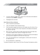
INSTALLATION Installation Instructions The TriFlex booster is suited for installation in a building or home. Step 1: Connect the Outside Antenna 1. Mount the fiberglass antenna in an outside mounting location that: Has at least a 12-inch radius clear of obstructions and other radiating elements. Is at least 75 feet in a straight line from the inside antenna when used in an area prone to weak cellular signals and operating the booster at full 65dB gain.
INSTALLATION 2. Using the CM240 or CM400 cable, connect the inside antenna to the booster connector marked INSIDE (see page 4). 3. Hand tighten the connection. Step 3. Mount the Booster (Optional) 1. Select a location for your booster. 2. Clean the intended surface and allow it to dry. 3. Peel the protective paper from the back of the hook sides of the Velcro. Press the adhesive side of the Velcro strips into place on the bottom of the booster, one strip on each end. 4.
INSTALLATION Step 4. Connect to AC Power 1. Connect the AC power cord to the booster (see page 4). 2. Connect the plug on the other end to a 110V AC power outlet. Be sure all connections to the booster are tight and secure. The booster turns on automatically. The Power LED goes ON to show that the booster is ready for use (see page 4). The Alert LEDs flash up to 15 seconds on each band to show the band is activated (see page 4) The booster is rated for 5-20V input voltage.
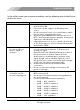
TROUBLESHOOTING Troubleshooting In the unlikely event you encounter a problem, use the following steps to identify and resolve the issue. Problem Booster has no power 1. 2. 3. 4. After installing the booster system, you have no signal or reception. 1. 2. 3. One of the red lights next to the dials on your booster is flashing red. 1. 2. 3. SureCall TriFlex - T Kit for Home Resolution Verify that the switch on the power supply is turned on and red LED is ON.
TROUBLESHOOTING Problem Your booster restarted and shut down for 15 minutes, and is now shut down permanently. The red LED goes ON. The Power LED does not turn ON. The Alert LEDs flash after the initial activation period. The Alert LEDs continue to flash. SureCall TriFlex - T Kit for Home Resolution Each SureCall booster is equipped with Auto Shutdown to prevent cell tower interference. The outside antenna may be close to a cell tower.
FREQUENTLY ASKED QUESTIONS Frequently Asked Questions For a list of Frequently Asked Questions and a comprehensive, up-to-date Troubleshooting Guide, please visit our website at: www.surecall.com or call us at 1-888-365-6283. Obtaining Technical Support You can also consult a SureCall technical specialist directly by emailing us at support@surecall.com.
WARRANTY Warranty Two-Year Product Warranty SureCall warrants its products for two years from the date of purchase against defects in workmanship and/or materials. Products returned by customers must be in their original, un-modified condition, shipped in the original or protective packaging with proof-of-purchase documentation enclosed, and a Return Merchandise Authorization (RMA) number printed clearly on the outside of the shipping container.
WARRANTY Limitations of Warranty, Damages and Liability: EXCEPT AS EXPRESSLY SET FORTH HEREIN, THERE ARE NO WARRANTIES, CONDITIONS, GUARANTEES, OR REPRESENTATIONS AS TO MERCHANTABILITY, FITNESS FOR A PARTICULAR PURPOSE, OR OTHER WARRANTIES, CONDITIONS, GUARANTEES, OR REPRESENTATIONS, WHETHER EXPRESSED OR IMPLIED, IN LAW OR IN FACT, ORAL OR IN WRITING. SURECALL AGGREGATE LIABILITY IN DAMAGES OR OTHERWISE SHALL NOT EXCEED THE PAYMENT, IF ANY, RECEIVED BY CELLPHONE-MATE, INC.
SPECIFICATIONS Specifications Specification TRIFLEX-T Uplink Frequency Range (MHz): Triflex-T: 1710-1755/824-849/1850-1910 Downlink Frequency Range (MHz): Triflex-T: 2110-2155/869-894/1930-1990 Supported Standards: Triflex-T: GSM, HSPA(+), AWS Input/Output Impedance: 50 Average Gain: 65dB Noise Figure: 5dB VSWR: 2.
SAFETY INFORMATION Safety Information This is a CONSUMER device. BEFORE USE, you MUST REGISTER THIS DEVICE with your wireless provider and have your provider’s consent. Most wireless providers consent to the use of signal boosters. Some providers may not consent to the use of this device on their network. If you are unsure, contact your provider. You MUST operate this device with approved antennas and cables as specified by the manufacturer.
48346 Milmont Drive Fremont, California 94538 USA 888.365.6283 Fax: 510.996.7250 www.surecall.com SureCall has made a good faith effort to ensure the accuracy of the information in this document and disclaims the implied warranties of merchantability and fitness for a particular purpose and makes no express warranties, except as may be stated in its written agreement with and for its customers.