Hardware Installation Guide Axess-Ready Compact Mount Surge Eliminator/Power Conditioner CM-1115(20)-RT-AR Software Version: 1.01.04 Firmware Version: 1.01.06 SurgeX • 517 North Industrial Drive, Zebulon, NC 27597 Customer Service: 800-645-9721 • Technical Support: 800-645-9721 • Fax: 919-269-0454 • www.surgex.
Table of Contents I. INTRODUCTION 3 II. INSTALLATION 5 PHYSICAL 5 ETHERNET CONNECTIONS 5 AC POWER CONNECTIONS 5 III. LED INDICATORS 6 IV. REMOTE CONTROL CONNECTIONS 6 V. VI.
Table of Contents VII. VIII. COMMAND LINE INTERFACE (CLI) PROTOCOL 18 PROMPTS 18 CONTROL COMMANDS 18 DEVICE COMMANDS 18 NETWORK COMMANDS 19 AUTOPING COMMANDS 20 USER COMMANDS 20 EVENT COMMANDS 21 DxP PROTOCOL 22 OVERVIEW 22 HELLO HANDSHAKE 22 DXP PACKET 23 COMMANDS 24 DESCRIPTORS 25 PAYLOADS 27 IX. FIRMWARE UPGRADES 28 X. RESET BUTTON 29 XI.
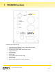
I. Introduction The SurgeX® CM-1115(20)-RT-AR is a network attached, IP addressed, web controlled AC surge eliminator and power conditioner. The CM-1115(20)-RT-AR may be used to switch up to 15A/20A at 120V. The simple web server structure allows basic control of two outlets. The extensive programming and setup capabilities are accessed by a web browser, through a Device Management Utility (DMU), or through a Command Line Interface (CLI).
I.
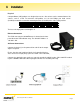
II. Installation Physical Compact Mount (CM) products are designed to rest on a flat surface or to be mounted onto a flat surface, such as a wall. To mount the CM product, use six 6-32 Phillips pan head screws (included) to attach the removable mounting brackets (included) to the sides of the product. Width CM-1115(20)-RT-AR 4.95" Depth 9.50" Height 6.16" Weight 9lb. The base unit input power cord length is 9’.
III. LED Indicators AXESS ON POWER OVER/UNDER VOLTAGE PROTECTION REMOTE SELF-TEST The Axess Ready system is On. The AR system must be on to enable hard-wired remote control connections. The RT system is On and the line voltage is within bounds. The line voltage is above 145V or below 90V and the outlets are Off. A hard-wired remote control signal is active and the outlets are On. The internal surge protection circuitry is fully functional. IV.
IV. Remote Connections (continued) Contact Closure/Latching Switch: The unit will power up when the contacts are closed, and power down when the contacts are open. Connect the two wires from the contacts or switch to Pin 1 (Contact Closure) and Pin 2 (Contact Closure / Applied Voltage +). Outlet control requires a combination of Axess Ready (AR) control via IP and Remote TurnOn/Off (RT) control via hard-wired connection.
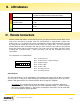
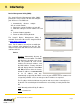
V. Initial Set-Up Device Management Utility (DMU) The SurgeX Device Management Utility (DMU) provides the easiest means to find and configure your AR for use. The DMU can: 1. Automatically discover multiple ARs on a local network. 2. Display the current IP address of each AR. 3. Allow the setting of a new IP address for each AR. 4. Perform firmware upgrades. 5. Return an AR to Factory Defaults. The SurgeX Device Management Utility is available on the AR CD or on the SurgeX website at http://www.surgex.
V. Initial Set-Up (continued) Manage Open Browser: Opens the web browser interface for the selected AR. Upgrade Firmware: Starts the Firmware Upgrade dialogue Firmware Upgrade Requirements Valid firmware file. Administrative login credentials. “Upgrade Enable” must be set to yet, set via web page or CLI Set IP Address: Changes the IP address of the selected AR Factory Defaults: Return the selected AR to a Factory Default state.
V. Initial Set-Up (continued) Example: Telnet to default IP address of 192.168.1.254 on default Port 23: SurgeX Axess Ready v1.01.41 User> admin Password> ***** Axess Ready> set ipaddress 10.1.2.69 Ok Axess Ready Reboot Required> set subnet 255.255.255.0 Ok Axess Ready Reboot Required> set gateway 10.1.2.1 Ok Axess Ready Reboot Required> reboot The CLI command set ipmode dhcp followed by a reboot command may be used to configure the AR to automatically acquire its network settings from a DHCP server.
VI. Web Server The Axess Ready web interface provides the easiest means of operating the outlet and changing configuration parameters. To access the web interface, open a web browser and enter the IP address of the AR into the address bar. The factory default IP address is 192.168.1.254. Password The AR uses two username/password credential sets, one for normal power control (user) and one that also provides access to the Setup functions (admin).
VI. Web Server (continued) Setup Pages Setup pages are only available while logged in with Administrator credentials. Press Save to save the new settings. If the new settings require the AR to be rebooted, a Reboot button will appear at the bottom of the page. Settings requiring reboot will not take effect until the unit is rebooted. Device • Location ID: Specifies a name label (up to 20 characters) that will be displayed at the top of all pages.
VI. Web Server (continued) Network • IP Mode: Select Static to manually set the IP address using the fields below, or choose DHCP to allow the AR to automatically acquire its network settings from a DHCP server. • IP Address: Enter a static IP address in dotted decimal format. This field will be automatically set if using DHCP. • Subnet Mask: Enter the Subnet Mask in dotted decimal format. This field will be automatically set if using DHCP. • Gateway: Enter the Gateway in dotted decimal format.
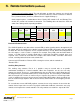
VI. Web Server (continued) AutoPing The AutoPing feature allows the AR to automatically detect failed equipment and perform a timed reboot or other power control function (like turning on an indicator or siren). First specify one or two IP addresses to be periodically pinged. When the AR no longer receives a response from these addresses, the programmed power control function is actuated.
VI. Web Server (continued) • Action: Select the action to be triggered. None Power On – Latch Power On – Follow Power Off – Latch Power Off – Follow Power Cycle Power Cycle - Once AutoPing not used Upon triggering, AR will power on and remain so until changed via web, telnet, or DxP. Upon triggering, AR will power on. When the ping response returns, AR will power off. Upon triggering, AR will power off and remain so until changed via web, telnet, or DxP. Upon triggering, AR will power off.
VI. Web Server (continued) Schedule The AR can schedule up to 8 recurring power events. For each event, you may define the starting date and time, the action to be taken, and the repetition interval (optional). Important: A Network Time Server (NTS) must be specified and enabled in order to use the time scheduling feature. A list of public time servers is available at http://www.ntp.org. • Enable: Checking the Enable box enables the time scheduling feature.
VI. Web Server (continued) Passwords Two passwords are used by the AR. The User password allows control of the AC receptacle state, but provides no access to Setup functions. The Administrator password allows full control and setup of the AR. Passwords may be up to 20 characters long, and are case sensitive. • Old Password: Enter the password currently in use. • New Password: Enter the new password to be used. • Confirm Password: Enter the new password to be used again.
VII. Command Line Interface (CLI) Protocol The Command Line Interface provides complete setup of all functions of the AR. The CLI may be accessed through the Telnet protocol, and requires a Telnet client program. Some commands of the CLI require administrative rights; these are indicated in the following tables. Prompts Prompt User> Description Prompts the user to enter the user name (either user or admin). Password> Prompts the user to enter the password. SX-iPD> Prompt displayed while logged in.
VII. Command Line Interface (CLI) Protocol (continued) Network Commands Command get network Description Returns all network settings currently in use. Example: Admin Yes Fact Def Mode: DHCP IP Address: 10.1.2.69 Subnet: 255.255.255.0 Gateway: 10.1.2.1 HTTP Port: 80 Telnet Port: 23 DxP Port: 9100 Timeout: 20 Ok set ipmode < static | dhcp > Sets the IP address mode. Static mode locks the IP address as set; DHCP mode allows a DHCP server to assign the address.
VII. Command Line Interface (CLI) Protocol (continued) AutoPing Commands Command get autoping set autoping < 1 | 2 > ipaddress < dotted decimal > set autoping < 1 | 2 > frequency < 1-999 > Description Returns all AutoPing settings currently in use. Example: AutoPing 1 AutoPing 2 IP Address: 10.1.2.36 0.0.0.
VII. Command Line Interface (CLI) Protocol (continued) Event Commands Command get events Description Returns all scheduled events currently in use. Example: Date Time Repeats Action 1. 12/22/2011 14:00 every 2 Hour(s) Cycle 2. every 0 Day(s) On 3. every 0 Day(s) On 4. every 0 Day(s) On 5. every 0 Day(s) On 6. every 0 Day(s) On 7. every 0 Day(s) On 8. every 0 Day(s) On Returns the current time and time server. Example: Current Time: 10:14:17 12/20/2011 Server: 10.1.2.
VIII. DxP Protocol Overview The DxP Protocol is a packet-based protocol designed to be extensible. This protocol is transmitted over TCP on a user-defined port. The factory default DxP port is 9100. The protocol uses a Hello handshake to establish unique sequence numbers to allow for advanced security when AES encryption is used. With AES enabled, all messages must be encrypted with the AES Passphrase set in the device. After the Hello, a Command and Response sequence follows.
VIII. DxP Protocol (continued) DxP Packet The packet is broken up into 2 parts: the Header and the Payload. Header The header is used to carry general information, such as is shown in the C programming structure below: typedef struct { eCmnd command; char[21] uName; char[21] password; uChar desc; uint16 seq; } THeader Variable command uName password desc param seq Description Enumerated type that tells the DxP server what class of command is being sent.
VIII. DxP Protocol (continued) Commands There are currently 7 command classes. All classes are defined in the C programming enumerated type definition below: typedef enum { eCmnd_null, eCmnd_set, eCmnd_get, eCmnd_io, eCmnd_keepAlive, eCmnd_rss, eCmnd_rcu } eCmnd; 0 1 2 Command eCmnd_null eCmnd_set eCmnd_get 3 4 eCmnd_io eCmnd_keepAlive 5 eCmnd_rss 6 eCmnd_rcu Description This is a null command and should not be sent to the server. This command is used to set programmable variables on the server.
VIII. DxP Protocol (continued) Descriptors Descriptors are used to describe the individual command within a command class, and the payload that the packet contains. All of the descriptors and their payloads are outlined by command class below. eCmnd_set The descriptors for this command class will be product specific. eCmnd_get The descriptors for this command class will be product specific.
VIII. DxP Protocol (continued) Descriptors (con’t) eCmnd_keepAlive typedef enum{ eKeepAlive_null; } eKeepAlive; Command eKeepAlive_null Description This is the only valid descriptor that the keep alive command supports. It is defined as null, as it carries no payload.
VIII. DxP Protocol (continued) Payloads TChangeRelay typedef struct{ unsigned char relay; unsigned char state; } TChangeRelay; Where relay is the number of the relay to be affected – 1 (For example, 0 for relay 1 and 1 for relay 2) and state sets the state of the relay (1=Energize; 2=Relax).
IX. Firmware Upgrades The AR can be upgraded via the network if the upgrade feature has been enabled. To perform a field upgrade, follow the steps below. Important: Upgrading the firmware with a minor upgrade (For example, 1.01.xx to 1.01.yy) will not alter the user defined settings. Major upgrades may or may not reset the AR to factory defaults. Check the release notes for the upgrade before making any changes. 1.
X. Reset Button The recessed reset pushbutton located on the front panel performs 3 functions as detailed below: Action Momentary 5 Second Push Hold while powering up Result Soft Reset. Will not affect outlet state. Reset to Factory Defaults. Hold until the “System On” LED is blinking, then Recovery Mode. Allows upload of new firmware to Factory Default IP address of 192.168.1.254.
XI. Specifications Physical CM-1115(20)-RT-AR Temperatue Humidity Range AC Load Rating CM-1115-RT-AR CM-1120-RT-AR Power Requirement (no load) UL 1449-2 Adjunct Classification Test Results Width Depth Height 4.95" 9.50" 6.16" 5 - 35° C 5% to 95% R.H., non-condensing Weight 9lb.