SurgeX Space Saver Product Line Compact Mount (CM) Versatile Rear Mount (VM) USER MANUAL
Space Saver Manual 1 DESCRIPTION ..................................................................................................................................... 3 2 FEATURES ........................................................................................................................................... 3 3 INSTALLATION .................................................................................................................................. 4 3.1 PHYSICAL DIMENSIONS ............
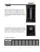
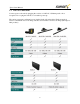
Space Saver Manual 1 Description The SurgeX® Space Saver products are 120V, 15/20 Amp AC power quality products incorporating SurgeX® Advanced Series Mode® power conditioning and surge protection. The surge protection is rated A-1-1, the highest standard of the Federal Commercial Item Description for Endurance. Several mounting options and receptacle configurations are available. SurgeX ICE® Inrush Current Elimination circuitry is incorporated into all of the Space Saver products.
Space Saver Manual 3 Installation Compact Mount (CM) products are designed to rest on a flat surface or to be mounted onto a flat surface, such as a wall. To mount the CM product, use six 6-32 Phillips pan head screws (included) to attach the removable mounting brackets (included) to the sides of the product. The attached power strip available with CM-1115(20)-RT18 and CM-1115(20)-RT24 is designed to rest on a flat surface or to be mounted along the side of a standard equipment rack.
Space Saver Manual 3.2 120 Volt Connections Connect power to the unit by plugging the cord into a 120V AC, 15/20 amp wall or floor receptacle. Do not plug the unit into a re-locatable power tap. The various receptacle configurations are detailed in the following tables. Each receptacle is rated for a maximum load of 15 Amps, but the total load must not exceed 15 Amps (20 Amps for 20A products).
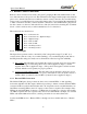
Space Saver Manual 3.3 Remote Control Connections Remote control connections are wired to the green 7-pin plug-in Phoenix terminal block on the rear of the unit next to the power cord. The terminal block is shipped with a jumper wire between pins 1 & 2 so that the unit can be used without a remote control connection. If you will be using remote control you will first need to remove this jumper wire.
Space Saver Manual 3.3.3 Auxiliary Relay Contacts The auxiliary relay contacts, Pins 6 & 7, provide a way to cascade units or to provide confirmation feedback to a central controller. When the switched receptacles are on, the aux relay contacts are closed. There is a 1 second delay before the aux relay closes, which allows time for the SurgeX Inrush Current Elimination (ICE™) circuit to operate.
Space Saver Manual 5 Specifications Operational Voltage Range: 90 to 150 Volts AC Current rating: 15/20 Amps Power Rating: 1,800/2,400 Watts Maximum Load Inrush Energy: 1000 Joules total during power-up Under-Voltage Shutdown: 90 V (resume at 100V) Over-Voltage Shutdown: 145V (resume at 135V) Surge Let-through Voltage: Zero let-through Voltage for a 6000 Volt surge Meets Federal Guidelines: Grade A, Class 1, Mode 1 (CID A-A-55818) EMI/RFI Filter, Normal Mode: 40 dB @ 100 KHz, 50dB @ 300