RP-IP RP-IP-GNS User Manual © 2014 Electronic Systems Protection, Inc. / Technical Support: 1-800-645-9721 / espei.
User Manual © 2014 Electronic Systems Protection, Inc. / Technical Support: 1-800-645-9721 / espei.
User Manual I. HARDWARE 3 A. RP-IP ............................................................................................................................. 3 B. RP-IP-GNS .................................................................................................................... 3 II. SETUP AND CONFIGURATION 4 A. IP SETTINGS AND CONFIGURATION ....................................................................................4 B. LAN OPERATION AND CONFIGURATION ............................
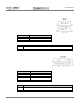
User Manual I. HARDWARE: A. RP-IP 1. LAN: Connect to local network using Cat5e patch cable 2. XG / EV Data Port: Connect to XG or EV product using 6p6c RJ25 patch cable with Standard pin out 3. Power: Input power connection. USB Mini B, 5VDC, 500mA minimum 4. LEDs: LED State Meaning EV, XG Toggle EV solid, XG off XG solid, EV off 5. Buttons: Button Reset Mode B.
User Manual II. SETUP AND CONFIGURATION: A. IP Settings and Configuration 1. Factory Default: Acquires IP address automatically via DHCP 2. Determine assigned IP address by one of the following methods: a. Access router table b. Download and run ESP RP-IP Discover Utility available on the Downloads tab here: http://www.espei.com/products/remote-portal c. Download and install Lantronix DeviceInstaller: http://www.lantronix.com/device-networking/utilities-tools/device-installer.html B.
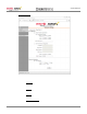
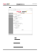
User Manual 2. Network Settings: View and change IP Configuration. a. Select Obtain IP address automatically to automatically receive an IP address (1) BOOTP: Select Enable to permit the Bootstrap Protocol (BOOTP) server to assign the IP address from a pool of addresses automatically. Enable is the default. (2) DHCP: Select Enable to permit the Dynamic Host Configuration Protocol (DHCP) to assign a leased IP address to the RP-IP automatically. Enable is the default.
User Manual b. Select Use the following IP configuration to manually specify the IP address. (1) IP Address: If DHCP is not used to assign IP addresses, enter it manually in decimal-dot notation. The IP address must be set to a unique value in the network. (2) Subnet Mask: A subnet mask defines the number of bits taken from the IP address that are assigned for the host part. (3) Default Gateway: The gateway address, or router, allows communication to other LAN segments.
User Manual 3. Server: View and change the embedded Server settings. a. PCS Communication (1) Mode: Select enVision (EV) or NextGen (XG) operational mode. (2) TCP Server Port: Specify the port for serial data. b. Server Configuration (1) Enhanced Password: Selecting this option enables advanced password creation, allowing you to create passwords up to 16 bytes in length. Disabling this option disables advanced password creation, allowing you to create basic passwords up to 4 bytes in length.
User Manual c. Advanced (1) ARP Cache Timeout: When the unit communicates with another device on the network, it adds an entry into its ARP table. ARP Cache timeout defines the number of seconds (1-600) before it refreshes this table. (2) TCP Keepalive: TCP Keepalive time defines how many seconds the unit waits during an inactive connection before checking its status. If the unit does not receive a response, it drops that connection. Enter a value between 0 and 60 seconds. 0 disables keepalive.
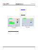
User Manual III. OPERATION: A. Java Applet 1. Download and install the current JRE from: www.java.com Java applet operation requires a computer with an operating system which supports the installation of a Java Runtime Environment (JRE), including MS Windows, Apple OSX, and various Linux distributions. 2. Using a web browser, navigate to the IP address of the RP-IP.
User Manual B. Mobile 1. When using a browser which does not support Java, a link to the mobile page will be provided. The mobile page requires that JavaScript be enabled. enVision PCS Mode C. Next Gen PCS Mode SNMP 1. The RP-IP and RP-IP-GNS provide monitoring and control via SNMP. The SNMP MIB may be downloaded here: http://www.espei.com/products/remote-portal D. COM Port Redirection 1.
User Manual IV. ADVANCED CONFIGURATION: A. Advanced settings may be adjusted via Telnet on port 9999. 1. Upon establishing a connection, the following information is displayed: *** ESP PCS *** MAC address 0080A39C878F Software version V6.9.0.3 (140902) CPK6903_XPT05 Press Enter for Setup Mode 2. To enter Setup Mode, press Enter within 5 seconds. The configuration settings display, followed by the Change Setup menu: enVision (EV) Mode *** basic parameters Hardware: Ethernet TPI IP addr - 0.0.0.
User Manual 6. Server configuration: Allows for the configuration of the following parameters: a. IP Address b. Gateway IP Address c. Netmask d. SNMP Manager IP Address e. Telnet configuration password f. DHCP device name g. DHCP FQDN option 7. Channel 1 configuration: Allows for the configuration of the following parameters: a. Connect Mode (Do not modify. Default is C0.) b. Source Port c. Destination Port (Currently Unused) d. Destination IP (Currently Unused) e. Enable Pack Control (Do not modify.
User Manual V. SPECIFICATIONS: Parameter Power Requirement Specification RP-IP RP-IP-GNS Network Interface Protocols Supported LEDs Dimensions Weight Temperature Range Humidity Range Agency Listings RP-IP RP-IP-GNS RP-IP RP-IP-GNS RP-IP RP-IP-GNS 5VDC, 2W 12VDC, 2W RJ45 Ethernet 10BASE-T or 100BASE-TX (auto-sensing) ARP, TCP/IP, Telnet, SNMP, DHCP, BOOTP, TFTP, Auto IP, and HTTP 10BASE-T & 100BASE-TX Link Activity, Full/half duplex. EV/XG mode indicators. 3.38” W x 2.2” D x 0.9” H 6.5” W x 2.