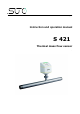
English Instruction and operation manual S 421 Thermal mass flow sensor
Dear Customer, Thank you for choosing our product. Please read this manual in full and carefully observe the operating instructions before starting up the device. The manufacturer cannot be held liable for any damage which occurs as a result of non-observance or non-compliance with this manual. Should the device be tampered with in any manner other than a procedure which is described and specified in the manual, the warranty is cancelled and the manufacturer is exempt from liability.
Table of contents 1. 2. 3. 4. Safety instructions.......................................................................4 Application.................................................................................7 Features.....................................................................................7 Technical Data............................................................................8 4.1 General.................................................................................8 4.
1. Safety instructions 1. Safety instructions Please check if this instruction manual accords to the product type. Please observe all notes and instructions indicated in this manual. It contains essential information which must be observed before and during installation, operation and maintenance. Therefore this instruction manual must be read carefully by the technician as well as by the responsible user / qualified personnel.
1. Safety instructions WARNING! Permitted operating parameters! Observe the permitted operating parameters, any operation exceeding this parameters can lead to malfunctions and may lead to damage on the instrument or the system. • Do not exceed the permitted operating parameters. • Make sure the product is operated in its permitted limitations. • Do not exceed or undercut the permitted storage and operation temperature and pressure.
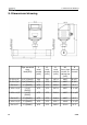
1. Safety instructions Storage and transportation 6 • Make sure that the transportation temperature of the sensor without display is between -30 °C ... 70 °C and with display between -10 °C ... 60 °C. • For storage and transportation it is recommended to use the packaging which comes with the sensor. • Please make sure that storage temperature of the sensor is between -10 °C ... 50 °C. • Avoid direct UV and solar radiation during storage.
2. Application 2. Application The S 421 is a flow sensor which is designed to measure the consumption of compressed air and gases within the permissible operating parameters. These parameters can be found in the technical data section. The S 421 can measure the following values: • Volume flow of the compressed air or gas. • Total consumption of the compressed air or gas. The default factory units are: Velocity in m/s, Volumetric flow in m3/h and Total Consumption in m3.
4. Technical Data 4. Technical Data 4.1 General Parameters Standard unit flow: m3/h Other units: m3/min, l/min, l/s, cfm, kg/h, kg/min, kg/s Consumption units: m3, ft3 , kg Reference conditions ISO1217 20 °C 1000 mbar (Standard-Unit) DIN1343 0 °C 1013.
4. Technical Data 4.2 Electrical Data Power supply 15 ... 30 VDC, 200 mA 4.3 Output-Signals Analogue output Signal: 4 ... 20 mA, isolated Scaling: 0 to max flow Max load: 250R Pulse output 1 pulse per consumption unit, isolated switch, max. 30 VDC, 200 mA (pulse length: 10 … 120 ms, depends on flow rate) Modbus output See chapter 9.3 4.4 Accuracy Accuracy ± 1.5% of reading ± 0.3% FS (optional 1% of reading) Temperature drift: < 0.
5. Dimensional drawing 5. Dimensional drawing Pipe nominal size inch(DN) L L1 H total length [mm] inlet length [mm] total height [mm] H1 R from pipe External center to thread casing top [mm] S 421-1/2” 1/2”/(DN15) 300 210 197.4 186.7 R 1/2” S 421-3/4” 3/4”/(DN20) 475 275 200.2 186.7 R 3/4” S 421-1” 1”/(DN25) 475 275 203.6 186.7 R 1” S 421-1 1/4” 1 1/4”/ (DN32) 475 275 207.9 186.7 R 1 1/4” S 421-1 1/2” 1 1/2”/ (DN40) 475 275 210.9 186.
5. Dimensional drawing Pipe L L1 nominal total inlet size length length inch(DN) [mm] [mm] H total height [mm] H1 from pipe center to casing top [mm] Flange (EN 1092-1 PN40) ØD (mm) ØK (mm) n x ØL (mm) S 421-1/2” 1/2”/ (DN15) 300 210 234.2 186.7 95 65 4xØ14 S 421-3/4” 3/4”/ (DN20) 475 275 239.2 186.7 105 75 4xØ14 S 421-1” 1”/ (DN25) 475 275 244.2 186.7 115 85 4xØ14 S 421-1 1/4” 1 1/4”/ (DN32) 475 275 256.7 186.
5. Dimensional drawing Pipe L L1 nominal total inlet size length length inch(DN) [mm] [mm] H total height [mm] H1 from pipe center to casing top [mm] Flange (ANSI/B16.5 class 300) ØD (mm) ØK (mm) n x ØL (mm) S 421-1/2” 1/2”/ (DN15) 475 275 234.2 186.7 95.2 66.5 4xØ15.7 S 421-3/4” 3/4”/ (DN20) 475 275 245.4 186.7 117.3 82.5 4xØ19 S 421-1” 1”/ (DN25) 475 275 248.7 186.7 123.9 88.9 4xØ19 S 421-1 1/4” 1 1/4”/ (DN32) 475 275 253.4 186.7 133.3 98.
6. Installation considerations 6. Installation considerations In order to maintain the accuracy stated in the technical data, the sensor must be installed inline and fitted to tubes with the same diameter. Please make sure it exists unhindered flow characteristics. Unhindered flow characteristics are achieved if the section in front of the sensor (inlet) and behind the sensor (outlet) is sufficiently long, absolutely straight and free of obstructions such as edges, seams, curves etc..
7. Inlet and Outlet sections 7. Inlet and Outlet sections The thermal measuring principle may be sensible to inlet and outlet conditions. For this we recommend the following minimum straight inlet and outlet sections to ensure an accurate measurement. Sensor should be always installed upstream from obstacles like valves, filter, reductions etc. In common the sensor should be installed as far as possible away from any disturbances.
7.
7. Inlet and Outlet sections 1. Expansion Section size LA (mm) DN15 DN20 DN25 DN32 110 160 270 440 DN15 DN20 110 160 270 DN15 DN20 DN25 DN32 110 160 DN15 DN20 DN25 DN32 DN40 DN50 DN65 DN80 560 790 1100 1300 2. Reduction Section size LA (mm) DN25 DN32 DN40 DN50 DN65 440 560 790 1100 DN80 1300 3. 90° Bend Section size LA (mm) 270 440 DN40 560 DN50 DN65 DN80 790 1100 1300 4. 2 x 90° Bend Section size LA (mm) 190 270 410 620 DN40 DN50 DN65 DN80 770 1100 1500 1700 5.
8. Sensor Installation 8. Sensor Installation Before installing the sensor, please make sure that all components listed below are included in your package. Qty Description Item No. 1 Sensor S695 4120 1 Sealing ring No P/N 2 M12 plug C219 0059 1 Instruction manual No P/N 1 Calibration certificate No P/N 1 Measuring section A1301 ... A1308 (R thread) A1321 ... A1328 (Flange, EN-1092-1) A1341 … A1348 (Flange, ANSI 16.5) The S 421 is always shipped with mounted measurement section.
8. Sensor Installation 8.1 Removal of the flow sensor The following steps explain the procedure of an appropriate removal of the sensor. ATTENTION! Only remove the sensor if the system is in a pressureless condition. 1. Hold the flow sensor. 2. Release the terminal nut at the connection thread. 3. Pull out the shaft slowly. 4. The measuring section can be closed with the optional closing cap, so the system can be operated normal during maintenance.
8. Sensor Installation 8.2 Electrical connection The flow sensor is equipped with two connector plugs “A” and “B”. The cables are connected to the sensor through the M12 connector.
8. Sensor Installation Legend to pin assignment GND: Ground for Modbus SDI: Digital signal (internal use) -VB: Negative supply voltage +VB: Positive supply voltage +I: Positive 4 ... 20 mA signal -I: Negative 4 ... 20 mA signal +P: Pulse output SW: Isolated pulse output DIR Flow direction input D+: Modbus data + D-: Modbus data - M: M-Bus data NA: Not applicable ATTENTION! Do not screw the M12 plug using force. Otherwise, it may damage the connecting pins.
9. Sensor signal outputs 9. Sensor signal outputs 9.1 Analog output The sensor has an analog output range of 4 ... 20 mA. This output can be scaled to match a desired measuring range. Standard scaling is from 0 to max flow. The corresponding flow in different pipe sizes can be found in Appendix A. For other ranges, please contact the manufacturer. 9.2 Pulse output The sensor sends out one pulse per consumption unit.
9. Sensor signal outputs If the flow rate is too high, the S 421 cannot output the pulses with default settings (one pulse per consumption unit). In this case, the pulse can be set by our service software or a connected display to 1 pulse per 10 consumption units or 1 pulse per 100 consumption units. For example, if set to 1 pulse per 10 m3, the sensor sends one pulse each 10 m 3. Example (1 pulse per 10 m3): 22 Volumetric flow [m3/s] Volumetric flow [m3/h] Pulse length [ms] Max.
9. Sensor signal outputs 9.2.
9. Sensor signal outputs 9.3 Modbus output Mode : RTU Baud rate : 19200 Device address : 1 Framing / parity / stop bit : 8, N, 1 Response time : 1 second Response delay : 0 ms Inter-frame spacing : 7 char Remarks You can change Modbus communication settings using the S4C-FS Service App and the optional local display. For instructions, see the next two chapters. Index Channel description Resolution Format Length Modbus address 1 Flow 0.
10. Sensor display (option) 10. Sensor display (option) The Sensor display shows values of the flow and the consumption. Moreover it shows error messages and enables you to change the configuration settings for the sensor. “Enter key” = “Up key” = “Down key” = 10.1 Starting process After powered up, the display starts automatically with an initialization procedure. During the next eight seconds the display shows the current software version and starts to build connection with the sensor.
10. Sensor display (option) 10.2 Configuration using the display The following settings can be changed via display or service software. • Gas type – select the gas to be measured. • Flow unit – select unit for flow value. For this please observe the following steps: 1. Press “Enter” (>3s) key to check and change settings (unlock code:12). 2. Use the “Up” and “Down” key on the keyboard to choose the setting which should be changed. 3.
11. Service App—S4C-FS 11. Service App—S4C-FS To change any setting on the S 421, please download the service app from the Google Play. This app runs on any Android system with BlueTooth supported. To change settings, the app needs to scan the QR code on the calibration certificate at first. This ensures that only valid users can access the sensor settings.
12. Calibration 12. Calibration The sensor is calibrated ex work. The exact calibration date is printed on the certificate which is supplied together with the sensor. The accuracy of the sensor is regulated by the on-site conditions, and parameters such as oil, high humidity or other impurities can affect the calibration and furthermore the accuracy. However we recommend you calibrate the instrument at least once per year. The calibration is excluded from the instruments warranty.
15. Warranty 15. Warranty SUTO provides a warranty for this product of 24 months covering the material and workmanship under the stated operating conditions from the date of delivery. Please report any findings immediately and within the warranty time. If faults occur during the warranty time, SUTO will repair or replace the defective unit, without charge for labour and material costs but there is a charge for other service such as transport and packing costs.
Appendix A Analogue output Appendix A Analogue output Scaling table of analogue output: Medium: Air at ISO 1217; 20°C; 1000 mbar Inch 1/2” 3/4” 1” 1 1/4” 1 1/2” 2” 2 1/2” 3” Tube Nominal Diameter DN 15 DN 20 DN 25 DN 32 DN 40 DN 50 DN 65 DN 80 Flow mm 16.10 21.70 27.30 36.00 41.90 53.10 68.90 80.90 m3/h 90.0 170.0 290.0 500.0 700.0 1,000.0 1,500.0 2,500.0 m3/min 1.50 2.80 4.80 8.33 11.67 16.67 25.00 41.67 l/min 1500.1 2833.3 4833.4 8,333 11,667 16,667 25,000 41,667 l/s 25.00 47.20 80.60 138.89 194.
Appendix B Modbus communication example Appendix B Modbus communication example 03 (0x03) Read holding register Request Response Slave address 1 byte Slave address 1 byte Function code 1 byte Function code 1 byte Starting address 1 byte Hi Byte count 1 byte Starting address 1 byte Lo Register Hi 1 byte No. of points Hi 1 byte Register Lo 1 byte No.
Appendix B Modbus communication example 16 (0x10) Write multiple registers Request Response Slave address 1 byte Slave address 1 byte Function code 1 byte Function code 1 byte Starting address 1 byte Hi Starting address 1 byte Hi Starting address 1 byte Lo Starting address 1 byte Lo No. of registers Hi 1 byte No. of registers Hi 1 byte No. of registers Lo 1 byte No.
Appendix C LRC and CRC calculation Appendix C LRC and CRC calculation LRC generation The Longitudinal Redundancy Checking (LRC) field is one byte, containing an 8–bit binary value. The LRC value is calculated by the transmitting device, which appends the LRC to the message. The device that receives recalculates an LRC during receipt of the message, and compares the calculated value to the actual value it received in the LRC field. If the two values are not equal, an error results.
Appendix C LRC and CRC calculation LRC generation function static unsigned char LRC(unsigned char *auchMsg, unsigned short usDataLen) { unsigned char uchLRC = 0 ; while (usDataLen––) uchLRC += *auchMsg++ ; /* LRC char initialized */ /* pass through message buffer */ /* add buffer byte without carry */ return ((unsigned char)(–((char)uchLRC))) ; /* return twos complement */ } CRC generation The Cyclical Redundancy Checking (CRC) field is two bytes, containing a 16-bit binary value.
Appendix C LRC and CRC calculation 8. When the CRC is placed into the message, its upper and lower bytes must be swapped as described below. Placing the CRC into the message When the 16-bit CRC (two 8-bit bytes) is transmitted in the message, the low-order byte will be transmitted first, followed by the high-order byte.
Appendix C LRC and CRC calculation 0xFB, 0x39, 0xF9, 0xF8, 0x38, 0x28, 0xE8, 0xE9, 0x29, 0xEB, 0x2B, 0x2A, 0xEA, 0xEE, 0x2E, 0x2F, 0xEF, 0x2D, 0xED, 0xEC, 0x2C, 0xE4, 0x24, 0x25, 0xE5, 0x27, 0xE7, 0xE6, 0x26, 0x22, 0xE2, 0xE3, 0x23, 0xE1, 0x21, 0x20, 0xE0, 0xA0, 0x60, 0x61, 0xA1, 0x63, 0xA3, 0xA2, 0x62, 0x66, 0xA6, 0xA7, 0x67, 0xA5, 0x65, 0x64, 0xA4, 0x6C, 0xAC, 0xAD, 0x6D, 0xAF, 0x6F, 0x6E, 0xAE, 0xAA, 0x6A, 0x6B, 0xAB, 0x69, 0xA9, 0xA8, 0x68, 0x78, 0xB8, 0xB9, 0x79, 0xBB, 0x7B, 0x7A, 0xBA, 0xBE, 0x7E, 0x
S 421 37
S 421
S 421 39
FCC Statement: This device complies with part 15 of the FCC rules Operation is subject to the following two conditions: (1) this device may not cause harmful interference, and (2) this device must accept any interference received, including interference that may cause undesired operation. NOTE: The manufacturer is not responsible for any radio or TV interference caused by unauthorized modifications to this equipment. Such modifications could void the user’s authority to operate the equipment.
SUTO iTEC GmbH SUTO iTEC (ASIA) Co., Ltd. Werkstr. 2 79426 Buggingen Germany Room 10, 6/F, Block B, Cambridge Plaza 188 San Wan Road, Sheung Shui, N.T. Hong Kong Tel: +49 (0) 7631 936889-0 Fax: +49 (0) 7631 936889-19 Email: sales@suto-itec.com Website: http://www.suto-itec.com Tel: +852 2328 9782 Fax: +852 2671 3863 Email: sales@suto-itec.asia Website: http://www.suto-itec.com All rights reserved © 40 Modifications and errors reserved.