
Operation Manual
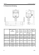
Table Of Contents
- 1. Safety instructions
- 2. Application
- 3. Features
- 4. Technical Data
- 5. Dimensional drawing
- 6. Installation considerations
- 7. Inlet and Outlet sections
- 8. Sensor Installation
- 9. Sensor signal outputs
- 10. Sensor display (option)
- 11. Service App—S4C-FS
- 12. Calibration
- 13. Maintenance
- 14. Disposal or waste
- 15. Warranty
- Appendix A Analogue output
- Appendix B Modbus communication example
- Appendix C LRC and CRC calculation

5. Dimensional drawing
5. Dimensional drawing
Pipe nominal
size
inch(DN)
L
total
length
[mm]
L1
inlet
length
[mm]
H
total
height
[mm]
H1
from pipe
center to
casing top
[mm]
R
External
thread
S 421-1/2” 1/2”/(DN15) 300 210 197.4 186.7 R 1/2”
S 421-3/4” 3/4”/(DN20) 475 275 200.2 186.7 R 3/4”
S 421-1” 1”/(DN25) 475 275 203.6 186.7 R 1”
S 421-1 1/4” 1 1/4”/
(DN32)
475 275 207.9 186.7 R 1 1/4”
S 421-1 1/2” 1 1/2”/
(DN40)
475 275 210.9 186.7 R 1 1/2”
S 421-2” 2”/(DN50) 475 275 216.9 186.7 R 2”
S 421-2 1/2” 2”/(DN65) 475 275 232.7 194.6 R 2 1/2”
S 421-3” 2”/(DN80) 475 275 245.5 201.0 R 3”
10 S 421