
Operation Manual
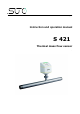
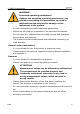
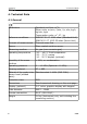
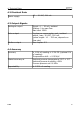
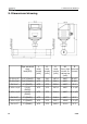
Table Of Contents
- 1. Safety instructions
- 2. Application
- 3. Features
- 4. Technical Data
- 5. Dimensional drawing
- 6. Installation considerations
- 7. Inlet and Outlet sections
- 8. Sensor Installation
- 9. Sensor signal outputs
- 10. Sensor display (option)
- 11. Service App—S4C-FS
- 12. Calibration
- 13. Maintenance
- 14. Disposal or waste
- 15. Warranty
- Appendix A Analogue output
- Appendix B Modbus communication example
- Appendix C LRC and CRC calculation

Table of contents
1. Safety instructions.......................................................................4
2. Application.................................................................................7
3. Features.....................................................................................7
4. Technical Data............................................................................8
4.1 General.................................................................................8
4.2 Electrical Data........................................................................9
4.3 Output-Signals.......................................................................9
4.4 Accuracy ..............................................................................9
5. Dimensional drawing..................................................................10
6. Installation considerations..........................................................13
7. Inlet and Outlet sections.............................................................14
8. Sensor Installation ....................................................................17
8.1 Removal of the flow sensor ...................................................18
8.2 Electrical connection ............................................................19
9. Sensor signal outputs.................................................................21
9.1 Analog output......................................................................21
9.2 Pulse output.........................................................................21
9.2.1 Pulse Connection Diagram................................................23
9.3 Modbus output.....................................................................24
10. Sensor display (option).............................................................25
10.1 Starting process..................................................................25
10.2 Configuration using the display.............................................26
11. Service App—S4C-FS................................................................27
12. Calibration..............................................................................28
13. Maintenance............................................................................28
14. Disposal or waste.....................................................................28
15. Warranty................................................................................29
Appendix A Analogue output...........................................................30
Appendix B Modbus communication example....................................31
Appendix C LRC and CRC calculation................................................33
S 421 3