
Operation Manual
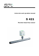
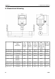
Table Of Contents
- 1. Safety instructions
- 2. Application
- 3. Features
- 4. Technical Data
- 5. Dimensional drawing
- 6. Installation considerations
- 7. Inlet and Outlet sections
- 8. Sensor Installation
- 9. Sensor signal outputs
- 10. Sensor display (option)
- 11. Service App—S4C-FS
- 12. Calibration
- 13. Maintenance
- 14. Disposal or waste
- 15. Warranty
- Appendix A Analogue output
- Appendix B Modbus communication example
- Appendix C LRC and CRC calculation

4. Technical Data
4.2 Electrical Data
Power supply
15 ... 30 VDC, 200 mA
4.3 Output-Signals
Analogue output Signal: 4 ... 20 mA, isolated
Scaling: 0 to max flow
Max load: 250R
Pulse output 1 pulse per consumption unit, isolated
switch, max. 30 VDC, 200 mA
(pulse length: 10 … 120 ms, depends on
flow rate)
Modbus output See chapter 9.3
4.4 Accuracy
Accuracy ± 1.5% of reading ± 0.3% FS (optional 1%
of reading)
Temperature drift: < 0.05%/K
Stated accuracy at Ambient/process temperature 23°C ± 3°C
Ambient/process humidity <90%
Process pressure at 0.6 MPa
Repeatability ± 0.25% of reading
S 421 9