EN SUUNTO VYTEC DS INSTRUCTION MANUAL
QUICK REFERENCE GUIDE
DEFINITION OF WARNINGS, CAUTIONS AND NOTES Throughout this manual, special references are made when deemed important. Three classifications are used to separate these references by their order of importance. WARNING - is used in connection with a procedure or situation that may result in serious injury or death. CAUTION - is used in connection with a procedure or situation that will result in damage to the product. NOTE - is used to emphasize important information.
PrEN 13319 PrEN 13319 ”Diving accessories – Depth gauges and combined depth and time measuring devices – Functional and safety requirements, test methods” is a European diving depth gauge standard draft. The VYTEC is designed to comply with this draft standard. ISO 9001 SUUNTO Oy’s Quality Assurance System is certified by Det Norske Veritas to be according to the ISO 9001 in all SUUNTO Oy’s operations (Quality Certificate No. 96-HEL-AQ-220).
WARNING! THERE IS ALWAYS A RISK OF DECOMPRESSION ILLNESS (DCI) FOR ANY DIVE PROFILE EVEN IF YOU FOLLOW THE DIVE PLAN PRESCRIBED BY DIVE TABLES OR A DIVE COMPUTER. NO PROCEDURE, DIVE COMPUTER OR DIVE TABLE WILL PREVENT THE POSSIBILITY OF DCI OR OXYGEN TOXICITY! An individual’s physiological make up can vary from day to day. The dive computer cannot account for these variations. You are strongly advised to remain well within the exposure limits provided by the instrument to minimize the risk of DCI.
WARNING! YOU ARE ADVISED TO AVOID FLYING ANY TIME THE COMPUTER COUNTS DOWN THE NO-FLYING TIME. ALWAYS ACTIVATE THE COMPUTER TO CHECK THE REMAINING NO-FLY TIME PRIOR TO FLYING! The computer goes into the stand-by display automatically 5 minutes after the dive has ended. The stand-by display shuts off after two hours. Flying or traveling to a higher altitude within no-fly time can greatly increase the risk of DCI. Review the recommendations given by Diver’s Alert Network (DAN) in chapter 3.6.3.
WARNING! THE DIVE COMPUTER WILL NOT ACCEPT FRACTIONAL PERCENTAGE VALUES OF OXYGEN CONCENTRATION. DO NOT ROUND UP FRACTIONAL PERCENTAGES! For example, 31.8% oxygen should be entered as 31%. Rounding up will cause nitrogen percentages to be understated and will affect decompression calculations. If there is a desire to adjust the computer to provide more conservative calculations, use the personal adjustment feature to affect decompression calculations or reduce the PO2 setting to affect oxygen exposure.
TABLE OF CONTENTS WARNINGS! .................................................................................................... 2 1. INTRODUCTION ......................................................................................... 8 1.1. SAFETY PRECAUTIONS ........................................................................ 9 1.1.1. Emergency Ascents ...................................................................... 9 1.1.2. Dive Computer Limitations ...........................................
4. 5. 6. 7. 8. 9. 3.8.1. Altitude Adjustment ...................................................................... 40 3.8.2. Personal Adjustment .................................................................... 40 3.9. ERROR CONDITIONS ........................................................................... 42 MENU BASED MODES ................................................................................ 43 4.1. MEMORIES AND DATA TRANSFER [1 MEMORY] ............................... 45 4.1.1.
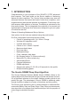
1. INTRODUCTION Congratulations on your purchase of the SUUNTO VYTEC advanced dive computer. The Vytec builds on the Suunto tradition of delivering feature-rich dive computers. The Suunto Vytec provides many new and enhanced features that cannot be found in other dive computers, such as gas switching and optional wireless air-integration. Push button controls access a wide selection of choices. The display is optimized for the dive mode chosen.
In order to optimize how to respond to different added risk situations an additional category of stop, referred to as a Mandatory Safety Stop, has been introduced. Also a countdown for the Recommended Safety Stop is included. The combination of stop types will depend on the specific dive situation. To get the most from the safety benefits be sure to read the summary of the Reduced. 1.1.
1.1.2. Dive Computer Limitations While the dive computer is based on current decompression research and technology, you must realize that the computer cannot monitor the actual physiological functions of an individual diver. All decompression schedules currently known to the authors, including the U.S. Navy Tables, are based on theoretical mathematical models, which are intended to serve as a guide to reduce the probability of decompression illness. 1.1.3.
The timekeeping display is the default display of the instrument (Fig. 2.1.). If a button is not pressed within 5 minutes, the dive computer beeps and returns to the timekeeping display automatically (except in Diving and Simulation modes). The timekeeping display shuts off after two hours, but pressing the PLAN or TIME button activates it. Making the Vytec personal For best use of the Vytec take some time and make it YOUR computer. Set the correct time and date. Read this manual.
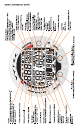
Press the SMART (MODE) button • To activate the dive computer. • To change from the Surface Mode to the menu based modes. • To select, confirm or quit a submode (short press). • To immediately exit any submode to the Surface Mode (long press). • To activate the electroluminescent backlight (in the Surface Mode hold down the mode button for more than two (2) seconds, during a dive for one (1) second). • To activate the gas change mode during a dive hold down the mode button for more than two (2) seconds.
2.4. WIRELESS CYLINDER PRESSURE TRANSMISSION The Vytec can be used together with an optional wireless cylinder pressure transmitter that can easily be attached to the high-pressure port of the regulator (Fig. 2.5). By using the transmitter the diver can benefit from cylinder pressure and remaining air time data. In order to use the transmitter the wireless integration needs to be enabled in the Vytec’s settings. To enable or disable the wireless integration refer to chapter 4.3.3.
2.4.2. Pairing and Code Selection In order to receive wireless data the transmitter and the Vytec wrist unit need to be paired. During the pairing procedure the transmitter and wrist unit select a common transmission code. The transmitter turns on when the pressure exceeds 15bar [218 psi] and it then starts sending pressure data together with a code number. During the pairing procedure the Vytec stores the above mentioned code number and starts displaying pressure values that are received with that code.
The selected transmission code can later be verified via the alternative display, by pressing the “TIME” button twice. If needed, the stored code can be manually erased in this display by pressing the “PLAN” (up) button and then pressing “MODE” (select). The Vytec will now erase the stored code and start displaying “SETC” allowing a new pairing with the transmitter. The alternative display showing the selected code reverts to the main display after 15 seconds in order to avoid accidental code changes.
In case the transmitter battery is running low, a low battery warning “LOBT” will be transmitted and displayed intermittently with the pressure reading on the Vytec (Fig.2.6 d). If the dive is started without that the Vytec and the transmitter have been properly paired, the Vytec will indicate that no cylinder data is available by displaying “OFF” (Fig. 2.6 e). TABLE 2.1. PRESSURE TRANSMISSION RELATED DISPLAYS Display Indication Figure 2.6 SETC Set Code.
3. DIVING WITH THE VYTEC This section contains instructions on how to operate the dive computer and interpret its displays. You will find that this dive computer is easy to use and read. Each display shows only the data relevant to that specific diving situation. 3.1. BEFORE DIVING DIVE m ft NO O2%SURF CEILING S L O AVGPO2 MAX W STOP ASC TIME QUIT OK AIR TIME OLF C B T °F °C bar SELECT NO DEC TIME psi OPTIONS DIVE TIME Fig. 3.1. Startup I. All segments shown. 3.1.1.
• m • • bar DIVE TIME TIME °C Fig 3.3. Startup III. Surface mode. Depth and dive time are zero and cylinder pressure is 300 bar [4350 psi]. Pressing TIME button activates alternative display of temperature and current time. Fig. 3.4. Startup IV. Gauge mode. m the instrument displays correct units of measurement (Metric/Imperial) the instrument displays correct temperature and depth (0.0 m [0 ft]) the buzzer beeps IIf the optional wireless pressure trans-mitter is used (see chapter 2.4.
The Battery Power Indicator can always be seen when the Dive Mode is activated. The electroluminescent backlight will be on during the battery check. The following Table and Figure show the various warning levels. TABLE 3.1. BATTERY POWER INDICATOR Display Operation Figure 3.2 BAT + 4 segments + OK Normal, full battery. BAT + 3 segments Normal, battery power is getting low or the temperature is low.
If the battery symbol is displayed in the Surface mode or if the display is faded or weak, the battery may be too low to operate the dive computer and battery replacement is recommended. NOTE! For safety reasons the backlight cannot be activated when the low battery warning is indicated by the battery symbol. 3.1.2.2. Wireless Transmitter Battery Indicator The pressure transmitter sends out a lowbat (LOBT) warning when its battery voltage is getting low.
The surface interval must be at least 5 minutes for a dive to be considered a repetitive dive. Otherwise, it is considered a continuation of the same dive. The dive number will not change and the dive time will continue, where it left off (see also section 3.6.2. “Dive Numbering”). 3.1.4. User Definable Functions and Alarms This Vytec has several User Definable Functions and depth and time related alarms that you can set according to your personal preference.
3.2.2. Mandatory Safety Stop When the ascent rate exceeds 12 meters/min [40 ft] momentarily or 10 meters/min [33ft] continuously the micro-bubble build-up is predicted to be more than allowed for in the decompression model. The Suunto RGBM calculation model responds to this by adding a Mandatory Safety Stop to the dive. The time of this MandaFig. 3.7. Dive has just begun tory Safety Stop will depend on the severity of and no air time is shown. the ascent rate excess.
3.2.3. Deep Stops The Suunto Vytec allows the user to choose a deep stop algorithm instead or the traditional recommended safety stop. Deep Stops are decompression stops that occur deeper than traditional stops, with the purpose of minimizing microbubble formation and excitation. The Suunto RGBM model calculates deep stop iteratively, placing the first stop about halfway between the maximum depth and the ceiling depth.
• m MAX AIR TIME C B T NO DEC TIME bar DIVE TIME • • the Personal Adjustment setting on the left side of the center window with a diver symbol and + signs (P0, P1, or P2) (see Table 3.5.) the Diver Attention Symbol if attenuated RGBM has been set (see Table 3.3.) blinking Diver Attention Symbol if surface interval should be prolonged (see Table 3.3.) Fig. 3.10. Bookmark In addition with the optional wireless transmisactivation.
shown in the left center window of the display. The calculation is always based on the actual pressure drop in your cylinder and will automatically adapt to your cylinder size and current air consumption. The change in your air consumption will be based on constant one second interval pressure measurements over 30 - 60 second periods. An increase in air consumption will influence the remaining air time rapidly, while a drop in air consumption will increase the air time slowly.
Red Zone – As all of the bars appear (red zone), your no-decompression stop time has become zero and your dive has become a decompression stop dive (for more information see section 3.3.6. “Decompression dives”). 3.3.5. Ascent Rate Indicator The ascent rate is shown graphically along the right side of the display as follows: TABLE 3.2. ASCENT RATE INDICATOR Ascent Rate Indicator The equivalent ascent speed Example in Fig.
3.3.6. Safety Stops and Deep Stops If Deep Stops are not used a 3 minute Recommended Safety Stop is prompted after every dive to 10m depth (fig. 3.11). Continuous ascent rate violations will result in Mandatory Safety Stops (fig. 3.14). When enabled, Deep stops are calculated. The length of the recommended Deep Stop is indicated in seconds (fig. 3.15b) 3.3.7. Decompression dives When your NO DEC TIME becomes zero, your dive becomes a decompression stop dive, i.e.
plus • the time needed to reach the surface after the ceiling and safety stops have been completed. WARNING! YOUR ACTUAL ASCENT TIME MAY BE LONGER THAN DISPLAYED BY THE INSTRUMENT! The ascent time will increase if you: • remain at depth • ascend slower than 10 m/min [33 ft/min] or • make your decompression stop deeper than at the ceiling. These factors will also increase the amount of air required to reach the surface.
lift you above the ceiling. Suunto recommends that decompression takes place deeper than 4 m [13 ft], even if the indicated ceiling is shallower. NOTE! It will take more time and more air to decompress below the ceiling than at the ceiling. WARNING! NEVER ASCEND ABOVE THE CEILING! You must not ascend above the ceiling during your decompression. In order to avoid doing so by accident, you should stay somewhat below the ceiling.
DISPLAY ABOVE THE CEILING m CEILING ASC TIME AIR TIME C B T bar DIVE TIME Fig. 3.16. Decompression dive, below floor. Upward pointing arrow, blinking ASC TIME label and an audible alarm tell you to ascend. Minimum total ascent time including safety stop is 7 minutes. Ceiling is at 3 m [10 ft]. m 3.4.1.
on Nitrox use result in longer no-decompression times and shallower maximum depths than diving with air. As a safety precaution the oxygen calculations in the computer are made with an oxygen percentage of 1% + setO2% . When the dive computer is set in Nitrox mode the Dive Planning and Dive Simulation modes both calculate with the O2% and PO2 values that are currently in the computer. To set the Nitrox mixes refer to chapter 4.3 Set Modes.
m MAX O2% NO DEC TIME OLF bar DIVE TIME Fig. 3.22. Diving in Nitrox mode. The O2% is set to 32%. m MAX AIR TIME NO DEC TIME OLF bar DIVE TIME Fig. 3.23. Diving in Nitrox mode. After air time is less than 30 minutes O2% is substituted by Air Time display. m PO2 label NITROX, is shown after activation. In Dive Planning mode the Nitrox display shows (Fig. 3.21.
After five seconds the display will automatically revert to the original display. m 3.4.3. Oxygen Limit Fraction (OLF) In addition to tracking the diver’s exposure to nitrogen, the instrument tracks the exposure to oxygen, if set to Nitrox mode. These calculations are treated as entirely separate functions. The dive computer calculates separately for Central Nervous System oxygen toxicity (CNS) and Pulmonary Oxygen toxicity, the latter measured by the addition of Oxygen Toxicity Units (OTU).
set maximum oxygen partial pressure. Tissue calculation during dive is based on the mix you have selected. The Vytec allows gas change to enabled gas mixes during the dive. Gas change is made by the following procedure: • Press the MODE button until the Vytec starts to show blinking “MIX” instead of temperature/cylinder pressure in the lower left display (Fig. 3.27). • Scroll between enabled mixes with PLAN and TIME buttons • Mix number, O2% and PO2 for the mixes are shown when scrolling.
Tank pressure and ascent rate indicator are also displayed during the dive (Fig. 3.28.). Remaining Air Time, temperature and current time are shown in the alternative display when the TIME button is pressed. m MAX NOTE! If you dive with the Gauge mode, it is not possible to change between the modes within 48 hours. 3.6. AT THE SURFACE 3.6.1. Surface Interval An ascent to any depth shallower than 1.
Or when the TIME button is pressed once or twice: • the current time, shown as TIME instead of the DIVE TIME • the current temperature with °C for Centigrade [or °F for Fahrenheit] • the surface time in hours and minutes (separated by a colon), telling the duration of the present surface interval Fig 3.30. Surface interval, Sur(Fig. 3.30.) face time display. Pressing TIME • the desaturation/no-flying time in button once will show surface hours and minutes is shown next to time display.
in the Planning Mode will increment to the next higher number if another dive is made. TABLE 3.3. WARNING SYMBOLS 3.6.3. Flying After Diving The no-flying time is shown in the center window next to the airplane image. Flying or travelling to a higher altitude should be avoided at any time the computer counts down the no-flying time. NOTE! The airplane symbol is not shown on the stand-by display.
• • • If a diver had less than 2 hours total accumulated dive time in the last 48 hours, then a 12 hour surface interval before flying is recommended. Following any dive that required a decompression stop, flying should be delayed for at least 24 hours, and if possible, for 48 hours. Suunto recommends that flying is avoided until all the DAN and UHMS guidelines and the dive computer wait to fly conditions are satisfied. 3.7.
You are able to preset alarms before the actual dive. The user programmable alarms can be set for maximum depth, dive time and time. The alarms activate when: • The preset maximum depth is reached • continuous beep series for 24 seconds or until any button is pressed. • the maximum depth blinks as long as the present depth value exceeds the adjusted value. • The preset dive time is reached • continuous beep series for 24 seconds or until any button is pressed.
3.8. HIGH ALTITUDE DIVES AND PERSONAL ADJUSTMENT The dive computer can be adjusted both for diving at altitude and also to increase the conservatism of the mathematical nitrogen model. 3.8.1. Altitude Adjustment When programming the instrument for the correct altitude, you need to select the correct Altitude Mode according to Table 3.4. The dive computer will adjust its mathematical model according to the entered altitude mode, giving shorter no-decompression times at higher altitudes (see Section 6.1.
• • • • • • • cold exposure - water temperature less than 20 °C [68 °F] the diver is below average physical fitness level diver fatigue diver dehydration previous history of DCI stress obesity The Personal Adjustment Mode is indicated by a diver symbol and plus signs (P0 = a diver, P1 = diver +, or P2 = diver ++). Section 4.3.1.1. ”Altitude Adjustment and Personal Adjustment Setting” describes how the Personal Mode is adjusted.
mode (RGB50). See Table 3.6. To advise the diver that attenuated RGBM has been set, the Diver Attention Symbol is constantly displayed (Table 3.3.) TABLE 3.6. RGBM MODEL SETTINGS 3.9. ERROR CONDITIONS The dive computer has warning indicators that alert the user to react to certain situations that would significantly increase the risk of DCI. If you do not respond to its warnings, the dive computer will enter an Error Mode, indicating that the risk of DCI has greatly increased.
4. MENU BASED MODES To make yourself familiar with the menu based functions, please use your Quick Reference Guide supplied with the Vytec together with the information in this chapter. The main menu based functions are grouped under 1) memory, 2) dive simulation and 3) setting modes. THE USE OF THE MENU BASED FUNCTIONS QUIT OPTIONS Fig. 4.1. Main menu based Mode options. [3 MODE]. 1. Activate the menu based modes by pressing once the SMART (MODE) button in the Dive Mode (Fig. 4.1.). 2.
EXIT / QUIT! By pressing the SMART button for more than 1 second, any menu based function or submode can be quit and the dive computer will return directly to the Dive Mode. THE LIST OF THE MENU BASED MODES 1. MEMORIES AND DATA TRANSFER [1 MEMORY] 1. Logbook and Dive Profile Memory [1 LOGBOOK] 2. Dive History Memory [2 HISTORY] 3. Data Transfer and PC-Interface [3 TR-PC] 2. SIMULATION MODE [2 SIMUL] 1. Dive Simulator [1 SIMDIVE] 2. Dive Planning Simulator [2 SIMPLAN] 3. SET MODES [3 SET] 1.
4.1. MEMORIES AND DATA TRANSFER [1 MEMORY] The memory options (Fig. 4.5.) for this dive computer include the combined Logbook and Dive Profile Memory (Fig. 4.6. – 4.12.), Dive History Memory (Fig. 4.13. – 4.14.) and the Data Transfer and PC-Interface functions (Fig. 4.15.). The dive entry time and date is registered in the Logbook memory. Always check before diving that the time and date are correctly set, especially after traveling between different time zones. QUIT OPTIONS Fig. 4.5. Memory options.
page 2 DIVE S L O MAX W O2% The END text is displayed between the oldest and most recent dive. (Fig. 4.12.) STOP ASC TIME QUIT OLF °C Note that chronological sequence in the logbook is determined by the date, not by the dive number. DIVE TIME Fig. 4.8. Logbook, page II. Main dive related data. page 3 DIVE QUIT TIME bar Fig. 4.9. Logbook, page III. Surface interval time, average depth and consumed air indicated by ÄP. DIVE QUIT DIVE TIME page 4 Fig. 4.10. Logbook, page IV.
Page III (Fig. 4.9.) • dive number in the dive series • average depth • surface interval time before the dive • DP describing Cylinder pressure drop during the dive (if wireless transmission enabled (HP on)). Page IV (Fig. 4.10.
DIVE PROFILE MEMORY [PROF] DIVE MAX QUIT DIVE TIME Fig. 4.14. Dive History information. Total number of dives, dive hours and maximum depth. SELECT Fig. 4.15. Data Transfer mode. [3 TR-PC]. QUIT OPTIONS Fig. 4.16. Dive Simulation options. [2 SIMUL]. 48 The scrolling of the profile will start automatically when the Logbook page IV (PROF) is entered. With the default setting, the dive profile is recorded and displayed in 20-second increments with each display being shown for about three seconds.
4.1.3. Data Transfer and PC-Interface [3 TR-PC] The instrument can be connected to an IBM compatible personal computer (PC), using the optional PC-Interface and software. With the PCInterface unit, dive data from the dive computer can be downloaded to a PC. The PC software can be used for educational and demonstration purposes, for planning dives, and for keeping a complete record of your dive history with the instrument. Additional Logbook data can also be added.
NOTE! While in the Data Transfer mode, the connector/water contacts are used only for the data transfer. The Dive Mode IS NOT automatically activated if the contacts are submerged. SELECT Fig. 4.17. Dive Simulator mode. [1 SIMDIVE]. After you have finished the data transfer, press the SMART (Quit) to exit Data Transfer mode. If a button is not pressed or no data is transferred within 5 minutes, the instrument beeps and returns to the timekeeping display automatically. 4.2.
multiple gas mixes are set they will be changed as soon as allowed maximum depth is reached upon ascent and in the order of: MIX1, MIX2 and MIX3 To enter the Dive Simulator mode select MODE- 2 SIMUL- 1 SIMDIVE (Fig. 4.17. and 4.18.). 4.2.2. Dive Planning Simulator [2 SIMPLAN] The Dive Planning Simulator mode shows you the present no-decompression limits.
4.3.1. Dive Parameter Settings [1 SET DIVE] OK Fig. 4.23. Setting Altitude adjustment. Press scroll buttons to change altitude mode. OK Fig. 4.24 Setting Personal adjustment. Press scroll buttons to change personal mode. OK Fig. 4.25 Setting RGBM adjustment. Press scroll buttons to change setting. 52 To enter the Dive Parameter Setting Mode select MODE- 3 SET- 1 SET DIVE. The Dive Parameter Setting mode has two to four options depending on the dive computer mode.
Now you are able to select from the three altitude modes (Fig. 4.23.) and the three personal modes (Fig. 4.24.) and the two RGBM effect, full normal or limited attenuated, modes (Fig. 4.25.) and safety stop/deepstop 1 or 2 minutes (Fig. 4.25b). 4.3.1.2. Dive Time Alarm Setting [2 d ALARM] The instrument has one Dive Time Alarm Setting, which can be used for several purposes to add to your diving safety. The alarm can be set, for example, to your planned bottom time. Fig. 4.25b.
m PO2 O2% OK Fig. 4.28. Setting primary gas mix (MIX1). Oxygen percentage is 32%, oxygen partial pressure limit is 1.4 bar. The equivalent maximum depth is displayed as 32.8 m [107 ft]. Press scroll buttons to change oxygen percentage and to set oxygen partial setting value. Accept settings by pressing MODE (OK). When in the Nitrox Setting mode the equivalent allowed maximum depth based on the chosen setting will also be displayed.
4.3.2.2. Adjusting Date [2 AdJ DATE] To enter the Date Setting Mode select MODE3 SET- 2 SET TIME- 2 AdJ DATE. After entering this mode you are able to set the correct year, month and day in this order (Fig. 4.31.). NOTE! • The day of the week is automatically calculated in accordance with the date. • The date can be set within the range of Jan 1, 1990 to Dec. 31, 2089. OK Fig. 4.30. Adjusting Time. 4.3.2.3. Adjusting Daily Alarm [3 T ALARM] You can set one daily alarm in the dive computer.
NOTE! When the backlight turned OFF, it does not illuminate when an alarm is given. 4.3.3.2. Dive Computer Units Setting [2 UNITS] OK To enter the Dive Computer Units Setting mode, select MODE- 3 SET- 3 SET PREF- 2 UNITS. This will enable you to choose between metric and imperial units (Fig. 4.34.). TIME Fig. 4.33. Setting Backlight On Time. Press scroll buttons to change backlight on/off and to set time value. m 4.3.3.3. Wireless Transmission Settings [3 HP] ft OK °C °F Fig. 4.34.
5. CARE AND MAINTENANCE This SUUNTO dive computer is a sophisticated precision instrument. Though designed to withstand the rigors of scuba diving you must treat it with proper care and caution as any other precision instrument. 5.1. IMPORTANT INFORMATION WATER CONTACTS AND PUSH BUTTONS Contamination or dirt on the water contacts/connector or push buttons may prevent the automatic activation of the Dive Mode and cause problems during the data transfer.
• • • • Protect the unit from shock, extreme heat, direct sunlight, and chemical attack. The dive computer cannot withstand the impact of heavy objects like scuba cylinders, nor chemicals like gasoline, cleaning solvents, aerosol sprays, adhesive agents, paint, acetone, alcohol etc. Chemical reactions with such agents will damage seals, case and finish. Store your dive computer in a dry place when you are not using it.
computer, there is a leak. A leak must be corrected without delay, as moisture will seriously damage the unit, even beyond repair. SUUNTO does not take any responsibility for damage caused by moisture in the dive computer, if the instructions of this manual are not carefully followed. In case of a leak, immediately take the dive computer to an authorized SUUNTO dealer or distributor. 5.5. BATTERY REPLACEMENT 5.5.1.
TOOLS REQUIRED • • • A flat 1.5 mm screwdriver or a special tool for spring bars (K5857). Soft cloth for cleaning. Needlenose pliers or large screwdriver for turning securing ring. BATTERY REPLACEMENT The battery and the buzzer are located in the back of the instrument in a separate compartment, the parts of which are shown in Fig. 5.1. To change the battery, follow the procedure below: 1. Remove the computer from the console or boot. Wrist model: • Pull off the boot.
8. Check the condition of the O-ring; a defective O-ring may indicate sealing or other problems. Dispose the old O-ring, even if it seems to be in good condition. 9. Check that the battery compartment, battery holder and lid are clean. Clean with soft cloth if necessary. 10. Gently insert the new battery in the battery compartment. Check the polarity of the battery: the “-” mark should point toward the bottom of the compartment and the “+” mark upwards. 11.
• Assemble the shorter part of the strap. Use the spring bar tool or small screwdriver to compress the spring bars. Make sure that the spring bars get fully seated so they will not come off their holes. Console model: • Refit the dive computer in the console according the instructions of the console. CAUTION! Check after the first dives for possible moisture under the transparent battery compartment lid, indicating a leak.
CAUTION! Defects caused by improper battery installation are not covered by the warranty. BATTERY KIT The transmitter battery kit includes a 3.0 V CR ˚ AA lithium cell battery and a lubricated O-ring. When handling the battery do not make contact with both of the poles at the same time. Do not touch the metal surfaces of the battery with your bare fingers. TOOLS REQUIRED • A Phillips head screwdriver • Soft cloth for cleaning.
NOTE! It is imperative to wait at least 30 seconds before re-installing the transmitter battery. When the battery is re-installed the transmitter sends an overpressure (“---“) signal on code 12 for 10 seconds, after which it goes to normal operation, and shuts down after 5min. 9. Check that the new lubricated O-ring is in good condition. Put it in the right position in the o-ring groove. Be very careful not to get any dirt on the o-ring or its sealing surfaces. 10.
TABLE 6.1.
Before high altitude diving, the instrument must be set to the Altitude Adjustment mode to adjust the calculations for the new altitude. The maximum partial pressures of nitrogen allowed by the mathematical model of the dive computer are reduced according to the lower ambient pressure. As a result, the allowed no-decompression stop limits are considerably reduced. SURFACE INTERVALS The dive computer requires a minimum surface interval of 5 minutes between dives.
Also on repetitive dives adjustment may be applied to the maximum allowable nitrogen overpressure in each theoretical tissue group. Depending on circumstances Suunto RGBM will adapt the decompression obligations by doing any or all of the following: • Reducing no-decompression stop dive times • Adding Mandatory Safety Stops • Increasing decompression stop times • Advising an extended surface interval (Diver Attention symbol). Diver Attention Symbol – Advice to Extend Surface Interval.
• • • the blinking of the bar graph stops, when the PO2 is below 0.5 bar audible alarms are given and the actual PO2 value blinks when it exceeds the preset limit in dive planning the maximum depth according to the O2% and maximum PO2 selected. 6.4. TECHNICAL SPECIFICATION Dimensions and weight: Vytec: • Diameter: • Thickness: • Weight: 61mm [2.4in]. 28mm [1.1in]. 68g [2.4 oz]. Transmitter: • Max. diameter: 40 mm [1.57 in]. • Length: 80mm [3.15 in]. • Weight: 118g [4.16 oz].
Other displays: • Dive time: • • • • • • 0 to 999 min, counting starts and stops at 1.2 m [4 ft] depth. Surface time: 0 to 99 h 59 min. Dive counter: 0 to 99 for repetitive dives. No-decompression time: 0 to 199 min (- - after 199). Ascent time: 0 to 99 min (- - after 99). Ceiling depths: 3.0 to 100 m [10 to 328 ft]. Air time: 0 to 99 min (- - after 99). Displays only in Nitrox mode: • Oxygen%: 21 - 99. • Oxygen partial pressure display: 1.2 - 1.6 bar depending on the limit setting.
• and dive violations. The “M” values are tracked up to 100 hours after a dive. The EAN and oxygen exposure calculations are based on recommendations by R.W. Hamilton, PhD and currently accepted exposure time limit tables and principles. Battery Vytec: • One 3 V lithium battery: CR 2450 (K5597) and O-ring 1,78 mm x 31,47 mm 70 ShA (K5664). • Battery storage time (shelf life): Up to three years. • Replacement: Every two years or more often depending on dive activity. • Life expectancy at 20°C [68°F].
The following conditions have an affect on the expected battery lifetime: • The length of the dives. • The condition in which the unit is operated and stored (e.g. temperature/cold conditions). Below 10°C [50°F] the expected battery lifetime is about 50-75% of that at 20°C [68°F]. • The use of the backlight and audible alarms. • The quality of the battery (some lithium batteries may exhaust unexpectedly, which cannot be tested in advance).
made at the owner’s expense. This warranty is non-transferable from the original owner. All implied warranties, including but not limited to the implied warranties of merchantability and fitness for a particular purpose, are limited from date of purchase and in scope to the warranties expressed herein. Suunto shall not be liable for loss of use of the product or other incidental or consequential costs, expenses or damage incurred by the purchase. All warranties not stated herein are expressly disclaimed.
8.2. SUUNTOSPORTS.COM SECTIONS SuuntoSports.com includes three sections with several functions. The following paragraphs describe only the basic functions of SuuntoSports. com. You can find detailed descriptions of all the site functions and activities and step-by-step instructions for using them from the site Help. The Help is available on each page and its icon is located on the right side of the bar dividing the screen. The Help is frequently updated as the site develops. SuuntoSports.
All groups have a home page that displays information about group events and includes news, noticeboard and other information. Group members can also use group-specific bulletin boards, chat rooms and group calendars, and add links and create group activities. Sport Forums SuuntoSports.com has its own forum for each Suunto sport. The basic features and functions are the same for all sport forums—sport-specific news, bulletin boards and chat rooms.
9. GLOSSARY Air Time The amount of dive time remaining, based on a calculation of cylinder pressure and ambient pressure and present air consumption. Altitude dive A dive made at an elevation greater than 300 m [1000 ft] above sea level. Ascent rate The speed at which the diver ascends toward the surface. ASC RATE Abbreviation for ascent rate. Ascent time The minimum amount of time needed to reach the surface on a decompression stop dive. ASC TIME Abbreviation for ascent time.
Decompression Time spent at a decompression stop or range before surfacing, to allow absorbed nitrogen to escape naturally from tissues. Decompression range On a decompression stop dive the depth range, between the floor and ceiling, within which a diver must stop for some time during ascent. Decompression illness Any of a variety of maladies resulting either directly or indirectly from the formation of nitrogen bubbles in tissues or body fluids, as a result of inadequately controlled decompression.
Half-time After a change in ambient pressure, the amount of time required for the partial pressure of nitrogen in a theoretical compartment to go half-way from its previous value to saturation at the new ambient pressure. HP Abbreviation for high pressure (= cylinder pressure). Multi-level dive A single or repetitive dive that includes time spent at various depths and whose no-decompression limits are therefore not determined solely by the maximum depth attained.
O2% Oxygen percentage or oxygen fraction in the breathing gas. Standard air has 21% oxygen. Oxygen partial pressure Limits the maximum depth to which the used Nitrox mixture can safely be used. The maximum partial pressure limit for enriched air diving is 1.4 bar. The contingency partial pressure limit is 1.6 bar. Dives beyond this limit have the risk for immediate oxygen toxicity. PO2 Abbreviation for oxygen partial pressure. RGBM Abbreviation for Reduced Gradient Bubble Model.
Tissue group Theoretical concept used to model bodily tissues for the construction of decompression tables or calculations. Whole-Body Toxicity Another form of oxygen toxicity, which is caused by prolonged exposure to high oxygen partial pressures. The most common symptoms are irritation in the lungs, a burning sensation in the chest, coughing and reduction of the vital capacity. Also called Pulmonary Oxygen Toxicity. See also OTU.
DISPOSAL OF THE DEVICE Please dispose of the device in an appropriate way, treating it as electronic waste. Do not throw it in the garbage. If you wish, you may return the device to your nearest Suunto dealer.
SELECT OK sample rate 10, 20, 30, 60 s OK AIR,NITROX, GAUGE 4 REC 5 MODEL SELECT QUIT SELECT 2 SET TIME OK SELECT SELECT OK OK METRIC IMPERIAL OK QUIT OK OK QUIT OK decrease depth OK minutes on / off hours OK OK SELECT day OK month year 2 Adj DATE QUIT OK OK SELECT descend min hours OK 24h / AM / PM 1 Adj TIME ascend simulate diving QUIT dive simulation: surface mode C B T OK OK OK PO2 O2% MIX 1 MIX 2, ON/OFF MIX 3, ON/OFF SELECT MAX QUIT SELECT QUIT
Printed in Finland 08.
www.suunto.