Document No.: Bladder Scanner Model: M4-HD User Manual Version: M4-HD_V1.0.0.1 Product standard: XXX/J XXXX-2018 Production license No.: YSYJXSCX No. XXXXXXX Registration certificate No.: JSYJX (Z) ZI 2014 No. XXXXX Suzhou PeakSonic Medical Technology Co.Ltd.
Document No.: Contents User Manual.................................................................................................................................................................. 1 Version: M4-HD_V1.0.0.1 ........................................................................................................................................... 1 Contents .........................................................................................................................................
Document No.: 5.3 Main interface of the easy mode ............................................................................................................... 15 5.4 Main interface of the intelligence mode ................................................................................................... 16 5.5 Scanning under the expert mode .............................................................................................................. 16 5.5.1 Pre-scanning interface of the expert mode ...
Document No.: 6.2 wifi connection of tablet computer ................................................................................................................. 35 6.3 Bladder scanning ........................................................................................................... 错误!未定义书签。 6.3.1 Gender selection ............................................................... 36 6.3.2 Bladder pre-scanning ........................................................... 36 6.3.
Document No.: 7.2.2 Maintenance .................................................................. 61 7.3 Battery use and maintenance ................................................................................................................. 61 7.4 Disposal of electronic waste ................................................................................................................... 62 Chapter VIII Transportation and Storage .....................................................................
Document No.: Chapter I Overview Instructions: The right of interpretation of the document belongs to Suzhou PeakSonic Medical Technology Co.Ltd. No unit or individual may photocopy, copy or translate the document into other languages without the permission of the company. The rights to revise and modify the contents and terms of the document belong to the company. The revision and modification of the document will not be separately notified.
Document No.: scanning surface of the bladder. The position of the bladder shall be found before scanning (the operator does not need to have medical background, and moves the probe according to the real-time projection position). Position before scanning. During measurement, the instrument is non-invasive and comfortable to patients. It is accurate, reliable, rapid and simple in operation. When the user releases the scan key, within several seconds, it can get several 2D ultrasound images.
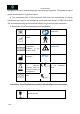
Document No.: the safety of ultrasonic medical diagnostic and monitoring equipment. The protection type of electric shock hazard is: Type B of Class II. ● The environment test of the instrument shall meet the requirements of climate environment test Group II and mechanical environment test Group II of GB/T14710-2009 The environmental requirements and test methods for medical electrical equipment. ● Description of instrument nameplate and identification: Product serial No.
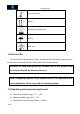
Document No.: Limit of temperature Upward Limit number of stacking layer Keep dry Avoid heat 1.4 Service life The service life of the product is 6 years. Continued use of this product after its service life will lead to increased fault rate of the product and unexpected risks. Warning: All risks arising from the continued use of this product after its service life shall be borne by the user. Note: Scrapping disposal of the product shall be in compliance with local regulations.
Document No.: 1.6 Statement on electromagnetic compatibility The use of M4-HD equipment will not affect the normal wired and wireless information transmission and the performance of other electronic equipment. It can work normally in the specified electromagnetic environment.
Document No.: manufacturer must be used. Warning: When charging the battery when it is in the instrument, the power supply of the instrument shall be disconnected, therefore, the instrument cannot be used during battery charging. 1.7 Statement of the manufacturer Responsibility of the manufacturer Suzhou PeakSonic Medical Technology Co.Ltd.
Document No.: 1.8 Contraindications Do not use the Bladder Scanner on following cases: a) Fetal use or pregnant patients. b) Patients with ascites. c) Patients with open or damaged skin. d) Wounds in the suprapubic region. 1.9 Release of heat index and mechanical index Heat index TIS: <0.042 TIB: <0.042 Mechanical index MI: <0.
Document No.: Chapter II Precautions In order to ensure safety, during the operation of the equipment, the following contents must be read first. This instrument is only allowed to be operated by a person confirmed or authorized by relevant medical institution. 2.1 Inspection before operation (1) The instrument is normal. (2) Do not keep the instrument close to hot or wet articles. Keep the instrument in place to ensure safe operation.
Document No.: fails, turn off the power immediately. (3) The patient is prohibited from touching the instrument or other electric appliances. (4) The vent of the instrument shall not be closed 2.4 Instructions after operation (1) Switch off the power. (2) Clean the instrument and the probe. (3) Place the instrument on the base. 2.
Document No.: water. 2.6 Relevant matters concerning moving the instrument (1) Turn off the power supply. (2) Drop, vibration and collision of the instrument are strictly prohibited. 2.7Operations in case of fault In case of malfunction of the instrument, turn off the power supply immediately, and contact with qualified maintenance personnel. 2.8 Inspect and maintain the instrument regularly 2.9 Do not disassemble the instrument and probe arbitrarily 2.
Document No.: Chapter III System Introduction 3.
Document No.: Charging socket Figure 3-3 Rear schematic diagram of M4-HD scanning device 3.2 Technical specifications ●Probe: 3D mechanical sector-scanning ●Nominal ultrasonic operating frequency: 2.
Document No.: database information), storage, printing, deletion and other operations ●Information input: Enter the gender, number, name and age of the patient ●Wifi wireless two-way transmission: The patient information is uploaded to the tablet computer for display, storage and printing. At the same time, a mutual transmission command is needed between the scanning device and the tablet computer.
Document No.: 3.
Document No.: 3.4 Basic principle This product is a non-invasive bladder scanner. On account of that ultrasonic diagnosis is a non-invasive examination method, this device first uses the principle and technology of ultrasonic imaging and obtains 12 images by using the 3D ultrasonic probe. It measures the bladder volume with the technology of drawing the bladder boundary points and conducting point integral operation at the same time. The method is as follows.
Document No.: received images will be displayed on the screen successively. With respect to displayed images, gray-scale modulation is conducted to the received sound beam signal intensity, achieving a plane image identical to the actual section. The reflected ultrasonic wave is received by the energy converter to convert the sound energy into electrical energy. This electrical signal is amplified and sent to the digital scanning converter (DSC) for filtering, detection and compression.
Document No.: output voltage range: 7.8-8.6V, 12.6W ●Base: Model BASE2 ●Tablet computer model: Samsung tablet computer A 10.5 SM-T590 10.5" 3GB+32GB WIFI business version ●User manual ●Lithium battery: model NCA653864SA-2400 mAh (PC015-2S1P) 7.4Vd.c.
Document No.: Chapter IV Instrument Installation 4.1 Unpacking inspection After the instrument is unpacked, first confirm that there is no transportation damage of the instrument, then inspect according to the "packing list" and install according to the requirements and methods specified in "4.2". 4.2 Installation 4.2.1Schematic diagram of the base for the scanning device of the instrument Figure 4-1 Schematic diagram of the base for M4-HD scanning device 4.2.
Document No.: ●Press the print key ①, and slide the printer fixation cover ② according to the reverse arrow direction to cover it. Disassembly of Bluetooth printer: ●Press the key ① ●Slide the printer fixation cover ② according to the arrow direction to remove it. ●And then press from the front to remove the Bluetooth printer ③ Figure 4-2 Schematic diagram of installation and disassembly of M4-HD printer 4.3 Power supply Power supply mode of the scanning device: battery powered. 4.3.
Document No.: (3) The power indicator light (red) on the charger is on. At this time, the battery is charged. When the charging indicator light turns green, the battery is fully charged. Printer battery is charged through the charger: (1) Plug the charger output plug into the DC 8.4V round hole socket on the base. (2) Plug the AC input plug of the charger into the power socket. (3) The power indicator light (red) on the charger is on. At this time, the battery is charged.
Document No.: Chapter V Instrument Interface 5.1 Startup interface A Figure 5-1 M4-HD startup interface A: Company LOGO and company name 5.
Document No.: K:Age input box P:Vertical line of the cross of the display L:Name input box area of the projection positioning diagram M: Current bladder volume value Q:Frame of 12 scanned ultrasonic images N: Projection positioning round frame R: Serial No. of 12 scanned ultrasonic O: Horizontal line of the cross of the display images area of the projection positioning diagram S: Real-time bladder ultrasound image display area 5.
Document No.: 5.4 Main interface of the intelligence mode B A C D E Figure 5-4 Main interface of M4-HD intelligence mode A: Positioning round frame area of the positioning diagram B: Display area of the positioning E: diagram Display area of B-ultrasound image C: Horizontal line of the cross of the display area of the positioning diagram D: Vertical line of the cross of the display 5.5 Scanning under the expert mode 5.5.
Document No.: 5.5.2 Scanning start interface of the expert mode Figure 5-5-2 Scanning start interface of M4-HD expert mode A: Represent the increase from 01, and when it becomes 12, represent the end of scanning and image analysis and calculation; Display bladder volume value B: The bladder image will be displayed one by one with the scanning progress, until 12 images are scanned and displayed. 5.5.
Document No.: 5.6 Scanning under the easy mode 5.6.1 Pre-scanning interface of the easy mode Figure 5-6-1 Pre-scanning interface of M4-HD easy mode A: Bladder scanning section area 5.6.2 Scanning start interface of the easy mode Figure 5-6-2 Scanning start interface of M4-HD easy mode 5.6.
Document No.: 5.7 Scanning under the intelligence mode 5.7.1 Pre-scanning interface of the intelligence mode Figure 5-7-1 Pre-scanning interface of M4-HD intelligence mode A: Real-time projection of bladder scanning B: 2D B-ultrasound image of bladder 5.7.2 Scanning start interface of the intelligence mode Figure 5-7-2 Scanning start interface of M4-HD intelligence mode Instructions: The scanning start interface of the intelligence mode is the same with that of the expert mode.
Document No.: 5.7.3 Scanning end interface of the intelligence mode Figure 5-7-3 Scanning end interface of M4-HD intelligence mode Instructions: The scanning end interface of the intelligence mode is the same with that of the expert mode. 5.8 Bladder projection interface of the expert mode Figure 5-8 Bladder 3D interface of M4-HD expert mode A: Display of 3D imaging diagram 5.
Document No.: 5.10 Bladder 3D interface of the intelligence mode Figure 5-10 Bladder 3D interface of M4-HD intelligence mode Instructions: The bladder 3D interface of the intelligence mode is the same with that of the expert mode. 5.11 Saved patient information browsing 5.11.
Document No.: 5.11.
Document No.: 5.11.3 Editing interface of patient history information Figure 5-11-3 Editing interface of M4-HD patient history information A: Edit patient ID code information B: Edit patient age information C: Edit patient name information 5.11.
Document No.: 5.11.5 Projection interface of patient history information Figure 5-11-5 Projection interface of M4-HD patient history information A: Enlarged display area of projection 5.11.
Document No.: 5.11.7 Upload login interface of patient history information Figure 5-11-7 Upload login interface of M4-HD patient history information A:Coded lock identification B:Input field of Upload Password C:Cancel login and return key D:Login key 5.11.
Document No.: 5.11.9 Single delete confirmation interface of patient history information Figure 5-11-9 Single delete confirmation interface of M4-HD patient history information A:Delete confirmation window C:Delete cancellation key B:Delete confirmation prompt D:Delete confirmation key 5.11.
Document No.: 5.12 System setting interface Figure 5-12 M4-HD system setting interface A: Mode selection setting G:System information view B: Calibration setting H:Setting interface window prompt C: Interface language setting I:View field of setting items D: Automatic poweroff time setting J:Confirmation field of setting items E: Volume alert setting K:Return to the main interface icon F:Password management 5.12.
Document No.: C:Easy mode selection option D: Intelligence mode selection 5.12.2 E: The operation mode is set as the expert mode confirmation item Calibration setting interface Figure 5-12-2 M4-HD calibration setting interface A: Select the calibration item from the setting list B: Bright Calibrate setting item C: Auto Calibrate setting item D: Auto Calibrate setting confirmation light is on in green and off in white.
Document No.: 5.12.
Document No.: Figure 5-12-4 M4-HD automatic poweroff time setting interface A : Select the automatic poweroff setting item from the setting list B: Select 5min poweroff C: Select 10min poweroff D: Select 15min poweroff E: Select 20min poweroff F: Turn off automatic poweroff function G: Automatic poweroff is set as close confirmation item 5.12.
Document No.: 5.12.6 Password management 5.12.6.1 Password management login interface Figure 5-12-6-1 M4-HD password management login interface A:Select the password management item password input field from the setting list D:Login key B:Coded lock mark C : Login password management and 5.12.6.
Document No.: management and new password input H:Light field of Memorize Password F:Administrator password I: Save key (press this key to save management and new password input the new password) field G: Light of Memorize History Info Password 5.12.6.3 wifi auto connect interface Figure 5-12-6-3 M4-HD wifi auto connect interface A:wifi auto connect prompt window B: Auto connect cancel key 5.12.
Document No.: D: Company name E: Key for entering the software version upgrade interface 5.12.7.1 Software version upgrade interface E D Figure 5-12-7-1 M4-HD software version upgrade interface A:Software version upgrade window B:Software version upgrade key 5.
Document No.: 5.14 Bluetooth auto connect interface Figure 5-14 M4-HD Bluetooth auto connect interface A:Bluetooth auto connect prompt window B: Auto connect cancel key 5.
Document No.: Chapter VI Operation Procedures 6.1 Instrument startup and shutdown Long press the power button of the scanning device to enter the startup state. Click the App icon on the tablet computer to display the startup interface. Stay at the startup interface for about 4 seconds, and then automatically enter the main interface. Long press the power button of the scanning device again to turn off the scanning device.
Document No.: startup, the tablet computer and the scanning device will automatically connect. If it is set as Auto Connect off (i.e., the manual connect) on the password management interface, under the manual connect mode, it can be set as Use Wifi Password on (i.e., Use Wifi Password is required for manual connect) on the password management interface. Use Wifi Password shall be entered for connecting the tablet computer and the scanning device after each startup.
Document No.: the center of the circle, and to maximize the bladder section area. When selecting the “intelligence mode”, during pre-scanning, the operator can observe the real-time bladder scanning projection position of the patient and move the probe to make the real-time bladder scanning projection move to the center of the circle. When the projection is displayed in green, it means that the bladder is in the scanning area; otherwise, it is in orange. Note: 1.
Document No.: from 01. When the serial number is 12, the scanning, image analysis and calculation are completed, and the image display area will automatically jump to the first scanned image. At the same time, the right side of the screen displays the 3D projection of the bladder and the current bladder volume value. The 12 scanned images are displayed at the bottom of the screen.
Document No.: bladder scanning treatment under the expert mode. 6.
Document No.: 6.6 Patient information saving After entering the patient information in 6.5 (or enter after saving the information), click the save icon on the main interface after the scanning is completed to save patient information. The saved patient information is encrypted. And after saving, a saved prompt message will pop up in the middle of the bottom of the image area.
Document No.: images. Note: The printing can be conducted only when the Bluetooth printer is connected with the tablet computer. When the Bluetooth printer is connected, the green icon will be displayed at the top of the main interface after scanning, indicating that the tablet computer has been connected to the Bluetooth printer; Otherwise, the icon is white, they are not connected. 6.
Document No.: 6.9.1 Patient history information view login Click Patients to enter the patient history information view login interface (Figure 5-14-1), enter the History Info Password in the login password input filed of the patient history information view login interface: 00000, and click the login key to enter the patient history information list interface for browsing information. Press cancel and return key to return to the main interface.
Document No.: the editing interface to input patient information, click save key after inputting to supplement and save information of the patient. After saving, it will automatically return to the main interface of patient history information. On the editing interface of patient history information, select certain patient information from the patient information list to print or delete the patient information. 6.9.
Document No.: select all key . At the same time, a translucent blue icon will cover the gender box of all patients. Finally, click the batch delete key , a prompt box will appear on the delete and upload batch information selection interface (i.e., form the batch information delete confirmation interface (Figure 5-11-10)) to prompt “Delete the selected items?”, and press “CONFIRM” to delete the information of the patient selected. Or press “CANCEL” key to undelete.
Document No.: input field of the history information upload login interface: 00000, click the login key to enter the upload prompt interface (Figure 5-11-8), prompting that the host computer connects according to the connection IP address (first 10 digits) on the prompt interface and the device port No. (last 4 digits). After successful connection, patient information starts to be uploaded. When uploading, the upload progress display appears in the middle of the upload prompt interface, such as xx/xxx.
Document No.: the scanning end interface (Figure 5-5-3 or Figure 5-6-3 or Figure 5-7-3), to enter the system setting interface (Figure 5-12). Setting parameters include: Operation mode selection, instrument calibration, interface language, automatic poweroff time, volume alert preset, password management and system information. Click return key on the system setting interface to return to the main interface. There are 7 options on the system setting interface, and the functions are as follows: 6.10.
Document No.: view the 3D image of the bladder. Or click the 3D images of the bladder to view the scanning projection. When the projection is displayed in green, it means that the bladder is in the scanning area; otherwise, it is in orange. When selecting the “intelligence mode”, during pre-scanning, the operator can observe the real-time bladder scanning 3D projection position and move the probe to make the real-time bladder scanning 3D projection move to the center of the circle.
Document No.: 6.10.4 Automatic poweroff time setting Click the "Auto Poweroff" on the system setting interface to enter the automatic poweroff time setting interface (Figure 5-12-4) to switch the automatic poweroff time to "5 min", "10 min", "15 min", "20 min" or "OFF". The default option is “5 min”, i.e., the instrument will shut down after 5 minutes automatically. After the selection, the " " will automatically appear in the setting item confirmation field behind the selected time.
Document No.: password management interface, the light of Memorize History Info Password is on in green. The system defaults to the login password. Therefore, no login is needed for viewing the patient history information. On the password management interface, the light of Memorize Upload Password is on in green. The system defaults to the login password. Therefore, no login is needed for uploading the patient history information.
Document No.: "21650", all passwords will be restored to the original password. 6.10.7 System information view Click the last item "System Info" on the system setting interface to enter the system information view interface (Figure 5-12-7), to show the current App Version: M4-HD_V1.0.0.1. Hardware Version: M4.V1.0.0.X. Company name: Suzhou PeakSonic Medical Technology Co.Ltd. System update prompt box . Click the return key to return to the main interface of the system. Note: 1.
Document No.: 6.11.1 Login host computer software Execute the PatientManager.exe to pop up the host computer login interface (Figure 6-1), and enter the original login password (default password 000000). Enter the host computer main interface If entering password "21650", the login password will be restored to the original password 000000.
Document No.: A B C D E F G H I K J Figure 6-2 Main interface of M4-HD host computer A: Import Data; B: Print; C: Save to PDF; D: Option; E: Patient age item; F: Patient gender item; G: Scanning date item; H: Bladder urine volume value item; I: Voice play item; J: Bladder image display area; K: Patient ID item 6.11.
Document No.: A B Figure 6-3 Data import mode selection interface of M4-HD host computer A: Wireless import from Wifi; B: Import from Usb cable 6.11.4 Host computer option interface Click the Option on the main interface of host computer, to pop up the drop-down menu, select Settings to pop up option interface dialog box and enter corresponding information in the input field, click Save to save and return, or click Cancel to cancel the operation and return.
Document No.: Figure 6-4 M4-HD host computer option interface A: Input field of hospital name; B: Input field of department name; C: Input field of doctor name; D: Cancel key; E: Save key 6.11.5 Host computer print interface Click the Print on the main interface of host computer, to pop up the print interface. The print interface includes the following information: Display 6 or 12 image selection box, print key, hospital name, department name, patient information, and bladder ultrasound images.
Document No.
Document No.: A Figure 6-6 M4-HD host computer print interface (12 images) A: 12 bladder ultrasound images 6.11.6 Save to PDF Click the Save to PDF on the main interface of host computer, to pop up the Save to PDF dialog box. Operations possible: Select the file save path, enter the file name, and select the file save type. Among them, the file save type can only be PDF (*.pdf).
Document No.: images at any time. The information of the PDF file is the same as the content printed by clicking the Print (6 or 12 images). 6.11.7 Host computer password change On the main interface of host computer, click option->password to enter the password change interface to change the password. Enter the old 6-digit password and enter the new 6-digit password twice. Press Save to successfully change the password.
Document No.: identifier). At this time, the power indicator of the scanning device is also yellow. When the battery is exhausted and the instrument is about to shut down, a “!” will appear in the red battery power identifier. ” 6.13 Scanning operation and bladder positioning Correct bladder positioning is the basis of accurate measurement of bladder volume. As shown in the figure on the right, the bladder lies in the hypogastrium of human body and below the symphysis pubis.
Document No.: scanning, positioning first and scanning later. The operation mode of positioning first and scanning later is realized. In the process of projection positioning, when the projection is green, it means that the bladder is in the scanning area. If the projection is orange, the measurement result may have error.
Document No.: Chapter VII Maintenance and Care To ensure the normal operation of the instrument, the instrument parts, accessories and probe shall be cleaned and maintained regularly. The material used for cleaning is neutral detergent. 7.1 Cleaning and maintenance of the system 7.1.1 Cleaning and disinfection steps (1) Turn off the system. (2) Use mild, nearly neutral detergent, ethanol (75%) or isopropanol (70%) to clean equipment (including keyboard).
Document No.: 7.2 Cleaning and maintenance of the probe Keep the probe clean to ensure that it can operate properly and to extend its service life. 7.2.1 Cleaning and disinfection steps (1) Check the probe, for example: Cracking, liquid leakage, etc. If there is obvious damage, do not continue to use the probe, and immediately contact Suzhou PeakSonic Medical Technology Co.Ltd. (2) Wipe the probe with neutral detergent, ethanol (75%) or isopropanol (70%). 7.2.
Document No.: automatically discharge slowly with time. Therefore, the battery that has not been used for a long time shall be charged first before use. (6) If the battery deforms, discolors or is hot or smelly, etc., stop using the battery immediately and remove it from the instrument or charger and dispose it according to the disposal regulations on scrapped battery. (7) There is a fuse in the attached battery charger, which is non-replaceable.
Document No.: Chapter VIII Transportation and Storage 8.1 Precautions for handling instrument (1) Place the instrument in corresponding place of the packaging box, strictly prevent falling, vibration and collision of the probe or the instrument. (2) After the packaging box is covered, it can be transported. Tighten the bottle cap of ultrasonic coupling agent to prevent the gel from flowing out and put it in corresponding place of the packaging box. 8.
Document No.: The interior shall be well ventilated and avoid intense sunlight and corrosive gas erosion.
Document No.: Chapter IX Simple Fault Inspection and Elimination 9.1 Inspection ●Inspect whether the power supply (battery) is installed. 9.2 Simple fault elimination Serial No. Fault phenomenon 1 Press the power button of the scanning device, but the indicator light is not on Inspect whether the battery is charged. 2 The key of the scanning device cannot be operated. Charge the scanning device with the charger and turn it on.
Document No.
Document No.
Document No.
Document No.
Document No.
Document No.: Appendix C Technical Specification for Electromagnetic Compatibility Table 201 Guideline and statement of the manufacturer-electromagnetic emission M4-HD bladder scanner is intended for use in the electromagnetic environment specified below. The purchaser or user shall ensure that it is used in such an environment. Emission test Compliance Electromagnetic environment-guideline RF emission GB 4824 1 group M4-HD bladder scanner uses RF energy only for its internal functions.
interruption and voltage change GB/T 17626.11 Power frequency magnetic field (50Hz) GB/T 17626.8 (on UT, >95% of sag) 40% UT, continuous for 5 weeks (on UT, 60% of sag) 70% UT, continuous for 25 weeks (on UT, 30% of sag) <5%UT, continuous for 5s (on UT, >95% of sag) Document No.: (on UT, >95% of sag) 40% UT, continuous for 5 weeks (on UT, 60% of sag) 70% UT, continuous for 25 weeks (on UT, 30% of sag) <5%UT, continuous for 5s (on UT, >95% of sag) typical commercial or hospital environment.
Document No.: transmitter supplied by transmitter manufacturer, in watt (W); Recommended isolation distance, in meter (m). Field strength of fixed radio-frequency transmitter shall be determined by electromagnetic field survey, and it shall be less than the compliance level in each frequency range. Interference may occur in the vicinity of equipment marked with the following symbols. Note 1: At the frequency points of 80 MHz and 800 MHz, the formula of higher frequency band shall be applied.
100 12 Document No.: 12 23 For the maximum rated output power of the transmitter not listed in the table above, the recommended isolation distance (d) in meter (m) can be determined by the formula corresponding to the frequency of the transmitter, wherein P is the maximum rated output power of the transmitter in watt (W) provided by the transmitter manufacturer. Note 1: At the frequency points of 80 MHz and 800 MHz, the formula of higher frequency band shall be applied.
Document No.: FCC Part15.19 This device complies with part 15 of the FCC Rules. Operation is subject to the following two conditions: (1) This device may not cause harmful interference, and (2) this device must accept any interference received, including interference that may cause undesired operation. FCC Part15.21 Changes or modifications not expressly approved by the party responsible for compliance could void the user's authority to operate the equipment. FCC Part15.
Document No.: Register: Suzhou PeakSonic Medical Technology Co.Ltd. 2F, Building G4, Kunshan Hi-Tech Medical Device Industrial Park, No.999 Qujia Road, Qiandeng Town Kunshan City, Jiangsu Province CHINA 215300 Manufactured by: SUZHOU LISCHKA MEDTECH CO., LTD. 2F,BuildingG4,Kunshan Hi-Tech Medical Device Industrial Park NO.999 Qujia Road, Qiandeng Town, Kunshan City Suzhou Jiangsu, CHINA 215300 After-sales service address: Kunshan Medical Equipment High-tech Industrial Park, Floor 2, Building G4, No.
Document No.: Attached page to the Specification Instructions for Auto Calibrate: The M series bladder scanner is patented in the fields of ultrasound imaging, measurement algorithm and probe. Therefore, the M series bladder scanner has the advantage of clinical application of no calibration required during the service life. For this, we officially state that: In the lifelong clinical application of the M series bladder scanner and the probe, as long as they are intact: 1.
Document No.: in the calibration confirmation interface prompt box to start Auto Calibrate. Auto Calibrate progress interface pops up at the same time. Press cancel key on the Auto Calibrate confirmation interface. Return to the Auto Calibrate interface. Step III: Auto Calibrate progress interface (Figure 3). The Auto Calibrate progress prompt is displayed on the interface, and the calibration result interface appears after the Auto Calibrate is completed.
Document No.: A B C D Figure 2 M4-HD Auto Calibrate confirmation interface A: Activate Auto Calibrate, with the Auto Calibrate switch light green.