
User's Manual


INSTALL MANUAL
Page 5 of 5
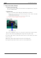
3.Connect the power wire
Plug power plug into master power socket, and fasten power wire with tie.
Note: Connect the red wire to anode 24V and black wire to cathode, screw the nut tightly.
Figure 8 Power Wire Socket
4
.Connect the communication wire
Plug DB9 connector into the Master socket, screw the nut tightly
Figure 9 Communication Wire Socket
Note: If no request, communication wire may not be installed.
5
.Error sign wire connection with PLC
Connect one end (DB9 pin) of the error sign wire to the DB9 socket and fasten the screw.
another end to the PLC I/O contact.
Note: Connect the red wire to contact end of the PLC I/O module, black wire to the PLC GND.
Caution Power Polar!
4.Introduction of LED indication
When the pressure information transmitted by Sensors inside 1-8 tires are received,
LED corresponding with tires on the Master will offer the corresponding indication. LED
indicates green when pressure is normal. When pressure of any tire is lower than the low
threshold of pressure, LED corresponding with tire will indicate red, at the same time
LED light will flash with buzzer beep.
When buzzer alarm, press any key on Master to stop beep, red LED will return into
green until pressure of tire recover normality and Master receive data of normal pressure.
When one of the sensors fails to work or Master could not receive the data for the
interference from RF in the certain time, LED corresponding with the sensor will go out