LCD KVM SWITCH User Manual
Statement LCD KVM Console User Manual United States Federal Communications Commission Interference Statement This product has been tested and found to comply with FCC regulations Class B (Class B) digital device and FCC specifications Details of Section 15.These specifications are intended to be used in a commercial environment without harmful interference and to provide for the protection of regulated equipment.
LCD KVM Console User Manual User Precautions The manufacturer has the right to modify and alter the information, documentation and specifications contained in this manual without prior notice. Manufactures makes no warranty, express, implied or statutory, disclaims or specifically disclaims it's possibility of sale and applicability for a particular purpose. The same applies to any sold and authorized manufacturer's software described in this manual.
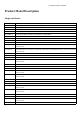
LCD KVM Console User Manual Product Model Description Single-rail Series Configuration instructions AS-7100ULS VGA Single portKVM,17inch 4:3 LED Monitor, No OSD Menu, Can be cascaded AS-7100DLS DVI Single port KVM,17inch4:3 LCD Monitor, No OSD Menu AI-7100ULS VGA Single portKVM,17inch4:3 LCD Monitor, No OSD Menu, Can be cascaded, IP Remote Control AS-9100ULS VGA Single portKVM,19inch4:3 LCD Monitor, No OSD Menu, Can be cascaded AS-9100DLS DVI Single portKVM,19inch4:3 LCD Monitor, No OSD Menu AI-9
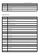
LCD KVM Console User Manual Remote Control AS-9116ULS VGA 16Ports KVM,19inch4:3 LCD Monitor, OSD Menu, Demountable Structure, Can be cascaded AS-9116TLS CAT5 16Ports KVM,19inch4:3 LCD Monitor, OSD Menu, Demountable Structure, Can be cascaded AI-9116ULS VGA 16Ports KVM,19inch4:3 LCD Monitor, SD Menu, Demountable Structure, Can be cascaded, IP Remote Control AI-9116TLS CAT5 16Ports KVM,19inch4:3 LCD Monitor, OSD Menu, Demountable Structure, Can be cascaded, IP Remote Control Dual-rail Series Model C
LCD KVM Console User Manual AS-7116TLD CAT5 16Ports KVM,17inch4:3 LCD Monitor, OSD Menu, Demountable Structure, Can be cascaded AI-7116ULD VGA 16Ports KVM,17inch4:3 LCD Monitor, OSD Menu, Demountable Structure, Can be cascaded, IP Remote Control AI-7116TLD CAT5 16Ports KVM,17inch4:3 LCD Monitor, OSD Menu, Demountable Structure, Can be cascaded, IP Remote Control AS-9116ULD VGA 16Ports KVM,19inch4:3 LCD Monitor, OSD Menu, Demountable Structure, Can be cascaded AS-9116TLD CAT5 16Ports KVM,19inch4:3
LCD KVM Console User Manual Package Contents The LCD KVM switch package includes the following: Name Quantity/unit Description LCD KVM Console 1/pc The LCD kit products KVM Cables N/pc Cables quantities according to the standard Port that selected Power 1/pc If it is built-in power supply products, power built-in. Power Cord 1/pc Standard 1.
LCD KVM Console User Manual Contents User Precautions........................................................................................................................................................................... 3 Product Model Description...........................................................................................................................................................4 Single Slide Series...................................................................................
LCD KVM Console User Manual Open Way of LCD Screen ................................................................................................................................................ 49 Chapter4......................................................................................................................................................................................51 OSD Operating..........................................................................................................
LCD KVM Console User Manual About this manual This User's Guide will assist you in the effective use of the product features, including the installation, setup and operation of the equipment. You will find the following in this manual: Chapter 1 Introduction - This chapter introduces the Rack KVM device system, including its functions, features, and advantages, and describes and introduces the front and rear panel components.
LCD KVM Console User Manual Description of Terms Symbol Indicates the text information that should be entered 【】The parentheses indicate the keys that need to be entered. For example, [Enter] means to press the Enter key. For keys that need to be entered at the same time, they are placed in the same bracket, and the keys are joined by a plus sign. E.g:【Ctrl+Alt】 1.Numbers indicate the actual operating sequence numbers.
LCD KVM Console User Manual Chapter 1 Introduction Products Introduction 4/8/16Ports USB/PS.2 LCD KVM Switch is a functional equipment that allows administrators to control 4/8/16pcs computers from a set of USB keyboards, mice, or a set of PS2 keyboards, mice.
LCD KVM Console User Manual The modular design and installation of the product series, you can freely replace the actual needs of the KVM components to facilitate the free combination of different applications. According to the module type can be divided into three categories: VGA device type, DVI device type, CAT5 type, Port number can be divided into 1, 4, 8, 16 .
LCD KVM Console User Manual Product Features 57 A group of USB console can manage 1, 4, 8 or 16 VGA or DVI interface computer control side supports USB and PS2 two interface types of keyboard, mouse device Can control two cascades ,cascade control up to 256 computers The front panel keypad, keyboard hotkey and on-screen menu (OSD) can be used to switch the computer connected with the accused device BIOS-level access, do not have to worry about th
LCD KVM Console User Manual Multi-window overlay technology can display multiple windows on the same remote console, and select and control any windows.
LCD KVM Console User Manual Computer-side DVI-I + USB (Type A)+ PS2 keyboard (purple) + PS2 mouse (green) LCD KVM switch single port VGA cable LCD Connector DB37P Computer-side VGA + USB (Type A) + PS2 keyboard (purple) + PS2 mouse (green) VGA + USB (Type A) + PS2 Keyboard (Purple) + PS2 Mouse (Green) 57
DVI-I + USB(Type A) + Audio KVM connection LCD KVM Console User Manual Computer connection Note: The cable length affects the quality of the display. If you need other lengths of cable, contact the merchant you purchased to purchase a cable suitable for this switch.
LCD KVM Console User Manual Operation System Operation System Windows Linux RedHat SuSE Debian Ubuntu UNIX AIX FreeBSD Sun Solaris Mac Novell Netware DOS Version Windows 2000/XP/2003/2008/Vista/7/10 9.0 or higher Fedora and above, RHEL AS 4, RHEL 5 10/11.1、OpenSUSE 10.2; SLES 10 SP1 3.1/4.0 7.04/7.10 4.3 or higher 5.5 or higher 8 or higher OS 9.0 to 10.6 (Snow Leopard) 6.0 or higher 6.
LCD KVM Console User Manual Parts Front View According to the size of the LCD screen is divided into two styles, as shown below, the components of the description please see the figure after the serial number table describes the details.
LCD KVM Console User Manual 4 5 6 LED screen KVM Module KVM Key panel 7 Front mounting brackets Touch Mouse Pad 8 9 10 11 12 Slide rails Keyhole LCD Keypad Panel Front USB angle of 0-110 degrees 17 "or 19" LED LCD screen KVM modules are free to replace and remove The KVM Port manual switch function is completed by pressing the key The LCD KVM can be installed on the cabinet posts with screws KVM console mouse, can control the computer's computer operation LCD module sliding track, can be telescopic f
LCD KVM Console User Manual LCD KVM 4 port CAT5 Rear View LCD KVM 8 port CAT5 Rear View LCD KVM 16 port CAT5Rear View LCD KVM 4 port DVI Rear View LCD KVM 8 port DVI Rear View According to the type of KVM ,the rear view of the product can be divided into three categories: VGA Port This type of LCD KVM switch can be divided into 4 models according to the number of ports: single port, 4 ports, 8 ports, 16 ports.
LCD KVM Console User Manual Front view of the 4: 3 screen and 16: 9 screen 17inch4: 3 screen 19inch 16: 9 screen 57
LCD KVM Console User Manual Single –rail &Dual-rail LCD Console display Single-rail LCD KVM Console Dual-rail LCD KVM Console 57
LCD KVM Console User Manual Dual -Rail Slide View Dual-rail overall rear view 57
LCD KVM Console User Manual Overall Dimensions of the LCD KVM Single-rail single port KVM Console dimension: 57
LCD KVM Console User Manual Single –rail multi-ports KVM Console dimension: 57
Dual-rail LCD KVM Console dimension: 57 LCD KVM Console User Manual
LCD KVM Console User Manual Chapter 2 Hardware Installation Stacking and Installation Precautions 1. Important safety information regarding the placement of the LCD KVM switch is listed in the appendix, please refer to it before proceeding. 2. Before installation, please make sure that all the devices connected to the power supply are turned off. You must unplug all the power cord of the computer with keyboard power on 3.
LCD KVM Console User Manual 2. Slide the LCD KVM unit onto the support flange, secure the front of the switch to the front of the rack with the screws provided in the package and lock.
LCD KVM Console User Manual 3.Slide the rear connecting slide bracket along the side rails until it reaches the rear of the switch. 4. Use the screws provided in this package to secure the strip to the rear of the switch. At this point, you have completed the rackmountable LCD KVM switch for subsequent use. Note: There may be a difference between the two-rail mounting bracket and the single-slide carriage. For the dual-rail product, please refer to the following figure.
LCD KVM Console User Manual KVM Module assembly & disassembly This series of LCD screen and keyboard, mouse and the rear part of the KVM part of the components can be demolished separation, this design allows you to change the KVM components, or KVM components damaged KVM components dismantled after the return to the manufacturer for repair and replace. Please refer to the figure for loading and unloading operations: 1.
LCD KVM Console User Manual 2. Remove the KVM assembly and the captive screws on the side brackets as shown to separate the KVM assembly from the front LCD assembly. 3.Please note the connector between the KVM module &LCD during the Removal and installation, or it may damage the connection interface and equipment function failure.
LCD KVM Console User Manual Disassembly of the Keyboard Module If you need to replace the LCD module part of the keyboard or repair this part, can also be demolished according to the following diagram. 1.The LCD KVM placed in the rack and fixed, the LCD panel turned up, revealing the keyboard, the mouse's operating surface. 2.The bottom of the keyboard panel has a circular hole, you can use your fingers through the circular hole, the top of the keyboard.
LCD KVM Console User Manual 3. Pull the keyboard from the limit slot gently, find the connection side of the USB interface, remove the USB from connection side, the keyboard could be taken out. Thus completing the demolition of the keyboard module. Note: If you replace the installation, please first plug the keyboard USB interface, then put the keyboard module into the limit slot.
LCD KVM Console User Manual with the dealer to buy our products supporting the IP module for equipment upgrades and expansion, the operation method is simple and quick, can quickly enhance the integrated management of KVM Application ability. 1. find the rear of the device, expansion slot outside the blank position for installation, you need to prepare a screwdriver for removal and installation tools. 2. Before installation, use a screwdriver to remove the two fixing screws on the blank. 1.
LCD KVM Console User Manual 2.Remove the extended IP module and push it gently into the recess in the mounting module cavity as shown. 3.After pushing the IP module to the bottom, fix the IP module with the two screws that have been removed before. 4. After installing the IP module, you need to follow the instructions of the IP module To install the software and configure the IP address of the device before you can connect the network cable to the switching device.
LCD KVM Console User Manual Single Device Installation Note:Before the installation, make sure that the equipment is powered off. To prevent damage to the equipment during installation, make sure that all the devices installed are well grounded. VGA port KVM module installation To install a single-level KVM, refer to the following online diagrams (numbered in the order of steps on the online graph) and do the following: 1.
LCD KVM Console User Manual CAT5 port KVM Module Installation To install a single-level KVM, refer to the following online diagrams (numbered in the order of steps on the online graph) and do the following: 1. Plug your USB keyboard and mouse into the USB console port on the back panel of the switch. 2.Use a set of CAT5e / 6-wire connectors to plug into any available CAT5 Port on the switch. 3.
LCD KVM Console User Manual DVI port KVM module installation To install a single-level KVM, refer to the following online diagrams (numbered in the order of steps on the online graph) and do the following: 1. Plug your USB keyboard and mouse into the USB console port on the back panel of the switch. 2. Insert the audio cable plug of the microphone and the speaker into the corresponding type port. 3.
LCD KVM Console User Manual Installation of Single Port LCD KVM Switch 57
LCD KVM Console User Manual Single-port LCD KVM switch choose KVM cables to connect instead of multi-port use KVM module, divided into two kinds: VGA and DVI according to the port type.
DVI single port LCD KVM Switch LCD KVM Console User Manual Note:Connect the DP37 port to the corresponding port on the back of the LCD, and then connect the video port of the other end to the video port of the computer. Then connect the port of PS2 or USB to the corresponding keyboard and mouse port of the computer, then power the computer and the LCD KVM switch.
LCD KVM Console User Manual CAT5 Port LCD KVM Switch Cascade In switch cascade mode, the keyboard, mouse and computer connections and stand-alone connection is the same, this part will not repeat them, the number part of the description is as follows: 1.The cascade KVM switch, have two connection methods, the use of USB KVM conversion module cable or PS2 KVM conversion module cable and a switch to the next level to connect.
LCD KVM Console User Manual The connection diagram is shown in the following figure (CAT5PortLCD KVM Switch Cascade).
VGALCD KVM Switch Cascade LCD KVM Console User Manual CAT5LCD KVM Switch Cascade 57
LCD KVM Console User Manual Chapter3 Basic Operation Hot Plug The KVM switch supports hot-plug, removing and removing components by unplugging the cables connected to the computer's port without shutting down the switch. To make the hot swap function work properly, follow these steps: Hot – Plug Computer Connection In order for OSD Menu to correspond to the KVM connection port changes, you must reset OSD Menu to display the latest connection port information, OSD menu settings.
LCD KVM Console User Manual KVM switch button located in the top of the keyboard operating area, divided into three blocks, from left to right in order is the online indicator display area, Port switch to select the display area, Port switch digital button area. Online Indicator Display Area The LEDs in the display area are lit when the controlled computer connected to KVM Port is connected to the line. The LED indicating the port number is illuminated and you can see the KVM online Port status.
LCD KVM Console User Manual KVM OSD Menu operation (Refer to the OSD Operation chapter for more information.
LCD KVM Console User Manual Open Way of LCD Screen When using, the LCD assembly can be unlocked from the side track by the handle of the upper part of the LCD unit. After unlocking, the LCD module can be pulled out from the slide rail. (Refer to the diagram above for operation) To open the LCD display screen, you can flip the screen upwards to fit the viewing angle only. The maximum angle that the LCD screen can be opened is 105 degrees -120 degrees. You can view the screen at any angle you like.
LCD KVM Console User Manual AUTO LOCK UNLOCK The screen will automatically pull out the slide after the brake lock device to prevent the random sliding LCD screen components to bring the instability and may cause damage to the user collision. After the brake lock is activated, the LCD screen will limit the operation of pushing the slide rail. If you want to do the push-in operation of the LCD module, the unlocking action must be done first, and the unlocking switch is on both sides of the slide rail.
LCD KVM Console User Manual Chapter4 OSD Operation OSD Introduction OSD (On Screen Display), provides a menu driven interface to handle the computer switching procedure to provide instant access to any computer on the installation. OSD Log in The OSD function provides a two-level (administrator / user) password mechanism.
LCD KVM Console User Manual OSD Main Menu Active OSD, following picture will be shown on the screen: 【F1】 --- 【F6】 at the bottom of the screen is the function setting of OSD menu, and corresponding operation and setting of corresponding function by keyboard. After entering the OSD main screen, the port number in the center of the screen is the port number of the selected PC. To move up and down through the list one line at a time, use the【↑】【↓】Arrow Keys, press 【Enter】 to select the switch port.
LCD KVM Console User Manual a port name; or make OSD setting adjustments. To activate the OSD function key: 1. Press any function key【F1】--- 【F6】 at the bottom of main screen to input the function key. 2. On the sub-menu, move the selection column to the option, and then press the {Enter} key. 3. Press the【Esc】key to return to the previous menu. F1 GOTO: Press the 【F1】 key to start the GOTO function.
LCD KVM Console User Manual Press [Space] to stop scanning, and the KVM switches to the port last scanned. F3 LIST: The LIST function lets you broaden or narrow the scope of which ports the OSD displays on the main screen. Many of the OSD functions only operate on the computers that have been selected for listing on the main screen with this function. The choices and their meanings are given in the table below: Choice Meaning ALL Lists all of the ports on the installation.
LCD KVM Console User Manual Move the highlight bar to a port, press [F4], an icon of up triangle appears. Press [F4] again, the icon disappears. F5 EDIT: EDIT function creates or edits the name of a port. Press [F5], a pink edit box will appear on the screen. Input name, and then press [Enter], the port is set a name and it will also appear on the screen. F6 SET: SET function settings can be set to the administrator and the user to set the OSD menu.
LCD KVM Console User Manual To change your settings: 1. Move the selection column to this option, press 【Enter】to enter a setting option. 2.After selecting an item, the sub-menu and the further options provided will appear. To select it, double-click the mouse or move the selection column to the option, and then press the [Enter] key, an icon will appear. Select the option before to indicate that the item has been selected.
LCD KVM Console User Manual OSD ACTIVATING HOTKEY It provides you with four hotkey combinations: You can use the keyboard 【↑】 【↓】 to move cursor to select, and then press 【Enter】 key to save. The default is to use 【CTRL】【CTRL】as the OSD menu start hotkey. SWITCH HOTKEY It provides you with four hotkey combinations: 【SCRLL】【SCRLL】【NUM】、【CTRL】【CTRL】【NUM】、【ALT】【ALT】【NUM】、 【SHIFT】【SHIFT】【NUM】You can use the keyboard 【↑】 【↓】 to move cursor to select, and then press 【Enter】key to save.
LCD KVM Console User Manual SCAN DURATION Duration for scanning one port. Options are 3 seconds, 5 seconds, 10 seconds, 15 seconds, 20 seconds, 30 seconds, 40 seconds, 60 seconds. Move the highlight bar to an option and press [Enter] to select it. SET PASSWORD Set new password. First enter old password, then enter new password and confirm it. The new password is set. If error occurs, the screen will remind users.
LCD KVM Console User Manual CLEAR THE NAME LIST This function clears the name of a port in the OSD menu. If you use this function, all the port names will be emptied, so please do it carefully. When doing this, you need to verify the password of the administrator, input 【Y】key, then press【Enter】 to confirm the operation. To cancel this operation, input【N】key, and then press【Enter】to confirm the cancel operation, or keyboard input 【Esc】 directly back.
LCD KVM Console User Manual Appendix Safety Instruction In General 57 This product is for indoor use only. Please read all the instructions for future reference. Follow all the warnings and instructions on the device. Do not place this equipment on any unstable surface (such as cart, stand, table, etc.). If this equipment falls, it will cause serious damage. Do not use this equipment near water.
LCD KVM Console User Manual The machine can’t be operated normally as instructed by the operating instructions. Adjustment only for the control functions covered by the operating instructions, and other inappropriate operations may cause damage, requiring more qualified personnel to perform repairs Cabinet Installation Before cabinet installation, make sure that the fixing device is securely fastened to the rack and extended to the ground. The weight of the whole rack can be dispersed on the floor.
Function Connectors Direct Cascade(Max) Port Selection Console Connectors Connectors Toggle Switch Video Keyboard Mouse Expansion Port Computer Monitor、 Port Keyboard, Mouse Power IP module network port Connection Port Selection KVM reset IPModule reset IP Module restored initially Computer Select port Computer Online port IP module network port Keyboard Mouse LED Indicator light Analog Mode Maximum resolution video Scan time interval Operation Operating temperature Environment Storage temperature Humi
LCD KVM Console User Manual CAT5 Series LCD KVM Switch Specification Function Computer Connections Connector Toggle switch Direct Cascade(Max) Port Selection Console Video Connectors Keyboard Mouse Expansion Port Computer Video Connectors keyboard& mouse conversion module Conversion module port Power IP module network port Connection Port Selection KVM reset IP Module reset IP Module restored initially Computer Select port Computer Online port IP module network port Keyboard Mouse LED Indicator light
LCD KVM Console User Manual DVI Series LCD KVM Switch Specification Function Connectors Direct Port Selection Console Monitor Port Keyboard Mouse Connectors Expansion Port Microphon e Audio speakers Computer Keyboard, Port Mouse Video Mixed audio port Power Toggle switch Connection Port Selection KVM reset LED Computer Select port Indicator light Computer Online port Analog mode Keyboard, Mouse Maximum resolution video Scan time interval Operation Operating temperature Environment Storage temperature Humi
LCD KVM Console User Manual LCD Module Specifications Function LCD Display Assembly LCD Screen Size Ratio LCD Screen Type Resolution Support color 17inch4:3 19inch4:3 19inch16:9 337.920(H) × 270.336(V) Wide AHVA TFT-LCD 376.32 (H) x 301.056 (V) 1980*1080@60HZ 16.7M color(RGB 6 bit + Hi_FRC) 16.7Mcolor,True 8 bit Backlight LED Nominal Voltage Input 408.96(H) x 230.04(V) 1280*1024@60HZ 1000 : 1 (Typ) LEDService life 0.264x0.297mm 0.294x0.294mm 300*300um 100,000Hours +5.
LCD KVM Console User Manual Warranty Conditions The Company shall not be liable for damages up to the amount paid by the Customer for the Products.