0.0 mm ENGLISH SERVICE STATION INFORMATION Fuel recommendation: See page 5-1 Brake and clutch fluid: DOT3 Engine oil recommendation: Engine oil with “Starburst” symbol Automatic transmission fluid: ESSO LT71141 or TOTAL ATF H50235 For further details, see “Engine Oil” in the “SERVICE AND APPEARANCE CARE” section. Tire cold pressure: See the “Tire Information Label” located on the driver’s door lock pillar. 2008 RENO Printed in U.S.A.
Prepared by July, 2007 Part No. 99011-85Z14-03E Printed in U.S.A.
This owner’s manual applies to the RENO series: 85Z005 NOTE: The illustrated model is one of the RENO series.
INTRODUCTION Thank you for choosing SUZUKI and welcome to our growing family. Your choice was a wise one; SUZUKI products are a great value that will give you years of driving pleasure. This Owner’s Manual was prepared to help you have a safe, enjoyable, and trouble-free experience with your SUZUKI. In it you will learn about the vehicle’s operation, its safety features and maintenance requirements. Please read it carefully before operating your vehicle.
SERVICE STATION GUIDE 1. 2. 3. 4. 5. 6. 7. 8. 9. 10.
TABLE OF CONTENTS California Proposition 65 Warning WARNING Engine exhaust, some of its constituents, and certain product components contain or emit chemicals known to the State of California to cause cancer and birth defects or other reproductive harm.
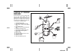
LOCATION OF WARNING MESSAGES 4 13 Read and follow all of the warnings (labels etc.) on your vehicle. Make sure you understand all of them. Keep them on the vehicle. Do not remove the messages for any reason. If a label comes off or the messages become difficult to read, have it corrected by your SUZUKI dealer. 1. Air Bag Warning Label 2. Passenger Air Bag Warning Label 3. Rear Center Safety Belt Warning Label 4. Jack Warning Label 5. Brake Reservoir Cap Warning Message 6. Cooling Fan Warning Label 7.
FOREWORD All information in this manual is based on the latest product information available at the time of publication. Due to improvements or other changes, there may be discrepancies between information in this manual and your vehicle. SUZUKI MOTOR CORPORATION reserves the right to make production changes at any time, without notice and without incurring any obligation to make the same or similar changes to vehicles previously built or sold.
IMPORTANT MODIFICATION WARNING WARNING/CAUTION/NOTE Please read this manual and follow its instructions carefully. To emphasize special information, the symbol and the words WARNING, CAUTION and NOTE have special meanings. Pay special attention to the messages highlighted by these signal words: WARNING Do not modify this vehicle. Modification could adversely affect safety, handling, performance or durability and may violate governmental regulations.
Vehicle Symbols Your vehicle has components and labels that use symbols instead of text. Symbols, used on your vehicle, are shown along with the text describing the operation or information relating to a specific component, control, message, gauge or indicator.
0-4 85Z14-03E
SEATS AND RESTRAINT SYSTEMS SEATS AND RESTRAINT SYSTEMS 1 Front Seats .......................................................................... 1-1 Rear Seats ............................................................................ 1-4 Safety Belts .......................................................................... 1-5 Child Restraints ................................................................... 1-15 Supplemental Restraint System (air bags) .......................
Front Seats: SEATS AND RESTRAINT SYSTEMS Front Seats If your vehicle does not have a sliding storage tray under the front seat, the manual seat bar looks like this. Manual Seats (With Sliding Storage Tray) WARNING Never attempt to adjust the driver’s seat or seatback while driving. The seat or seatback could move unexpectedly, causing loss of control. Make sure that the driver’s seat and seatback are properly adjusted before you start driving.
Front Seats: SEATS AND RESTRAINT SYSTEMS Driver Seat Height Adjuster Manual Lumbar Reclining Seatbacks Your vehicle may have manually operated lumbar support for the driver’s seat. N4U1003A To adjust the height of the driver’s seat cushion, turn the knobs located on the outboard side of the seat cushion. Turn the front knob to adjust the height of the front portion of the seat cushion. Turn the rear knob to adjust the height of the rear portion of the seat cushion.
Front Seats: SEATS AND RESTRAINT SYSTEMS Head Restraints Pull up the head restraint in order to adjust the position upward. L3U1009A Do not have your a seatback reclined when your vehicle is moving. WARNING All seatbacks should always be in a fairly upright position when driving, or seat belt effectiveness may be reduced. Seat belts are designed to offer maximum protection when seatbacks are in the fully upright position.
Front Seats: Rear Seats: SEATS AND RESTRAINT SYSTEMS Rear Seats 2) Push back firmly on the top of the seatback until it latches securely in the fully upright position. Folding Rear Seat Your vehicle has rear seatbacks that can be folded down to increase cargo space. To fold down the seatback, do the following: If the seatback isn’t locked, it could move forward in a sudden stop or crash. That could cause injury to the person sitting there. Always press rearward on the seatback to be sure it is locked.
Rear Seats: Safety Belts: SEATS AND RESTRAINT SYSTEMS WARNING • Do not stack luggage or other cargo higher than the front seats. • Do not allow passengers to sit on the folded seatbacks while the vehicle is in motion. • Unrestrained luggage or passengers on a folded seatback can be thrown about or ejected from the vehicle in a sudden stop or accident. Serious injuries or death can result. Safety Belts Safety Belt: They are for Everyone This section of the manual tells you how to use safety belts properly.
Safety Belts: SEATS AND RESTRAINT SYSTEMS Why Safety Belts Work When you ride in or on anything, you go as fast as it goes. L3U1017A L3U1015A Get it up to speed. Then stop the vehicle. The rider doesn’t stop. L3U1019A or the instrument panel... Take the simplest vehicle. Suppose it’s just a seat on wheels. L3U1020A L3U1018A or the safety belts! L3U1016A Put someone on it. The person keeps going until stopped by something. In a real vehicle, it could be the windshield...
Safety Belts: SEATS AND RESTRAINT SYSTEMS strongest bones take the forces. That’s why safety belts make such good sense. Questions and Answers About Safety Belts Question: Won’t I be trapped in the vehicle after an accident if I’m wearing a safety belt? Answer: You could be – whether you’re wearing a safety belt or not. But you can unbuckle a safety belt, even if you’re upside down.
Safety Belts: SEATS AND RESTRAINT SYSTEMS Shoulder Belt Height Adjuster Before you begin to drive, move the shoulder belt adjuster to the height that is right for you. Adjust the height so that the shoulder portion of the belt is centered on your shoulder. The belt should be away from your face and neck, but not falling off your shoulder. able to unbuckle the safety belt quickly if you ever had to.
Safety Belts: SEATS AND RESTRAINT SYSTEMS Question: What’s wrong with this? Question: What’s wrong with this? WARNING Be sure that the shoulder belt is positioned on the center of the outside shoulder. The belt should be away from your face and neck, but not falling off your shoulder. Misadjustment of the belt could reduce the effectiveness of the safety belt in a crash. L3U1025A Answer: The shoulder belt is too loose. It won’t give nearly as much protection this way.
Safety Belts: SEATS AND RESTRAINT SYSTEMS Question: What’s wrong with this? Question: What’s wrong with this? L3U1029A L3U1027A Answer: The shoulder belt is worn under the arm. It should be worn over the shoulder at all times. L3U1028A Answer: The belt is twisted across the body. WARNING WARNING You can be severely injured if you wear the shoulder belt under your arm. In a crash, your body would move too far forward, which would increase the chance of head and neck injury.
Safety Belts: SEATS AND RESTRAINT SYSTEMS Right Front Passenger Position Lap-Shoulder Belt To learn how to wear the right front passenger’s safety belt properly, see “Driver Position” in this section. All rear seating positions have lap-shoulder belts. Here’s how to wear one properly. The right front passenger’s safety belt works the same way as the driver’s safety belt.
Safety Belts: SEATS AND RESTRAINT SYSTEMS L3U1033A Pull up on the latch plate to make sure it is secure. Make sure the release button on the buckle is positioned so you would be able to unbuckle the safety belt quickly if you ever had to. L3U1034A 3) To make the lap part tight, pull down on the buckle end of the belt as you pull up on the shoulder part. L3U1023A The lap part of the belt should be worn low and snug on the hips, just touching the thighs.
Safety Belts: SEATS AND RESTRAINT SYSTEMS Safety Belt Pretensioner System WARNING You can be severely hurt if your shoulder belt is too loose. In a crash, you would move forward too much, which could increase injury. The shoulder belt should fit against your body. EXAMPLE 52D011 WARNING L3U1067A To unlatch the belt, just push the button on the buckle. This section of the owner’s manual describes your vehicle’s SAFETY BELT PRETENSIONER SYSTEM.
Safety Belts: SEATS AND RESTRAINT SYSTEMS impacts, side impacts, rollovers or minor frontal collisions. The pretensioners can be activated only once. If the pretensioners are activated, have the pretensioner system serviced by an authorized SUZUKI dealer as soon as possible. your SUZUKI dealer, body repair shop or scrap yard for assistance.
Safety Belts: Child Restraints: SEATS AND RESTRAINT SYSTEMS WARNING Failure to follow these instructions may increase the risk of injury in a crash. • Only use an extender for the person, vehicle and seating position it was provided for. • A front safety belt extender must only be used in a front seating position, and a rear safety belt extender must only be used in a rear seating position.
Child Restraints: SEATS AND RESTRAINT SYSTEMS Infants and Young Children Question: What if a child is wearing a lap-shoulder belt, but the child is so small that the shoulder belt is very close to the child’s face or neck? Answer: If the child is sitting in a seat next to a window, move the child toward the center of the vehicle. If the child is sitting in the center rear seat passenger position, move the child toward the safety belt buckle.
Child Restraints: SEATS AND RESTRAINT SYSTEMS Question: What are the different types of add-on child restraints? Answer: Add-on child restraints, which are purchased by the vehicle’s owner, are available in four basic types. Selection of a particular restraint should take into consideration not only the child’s weight, height and age but also whether or not the restraint will be compatible with the motor vehicle in which it will be used.
Child Restraints: SEATS AND RESTRAINT SYSTEMS Child Restraint Systems WARNING Newborn infants need complete support, including support for the head and neck. This is necessary because a newborn infant’s neck is weak and its head weighs so much compared with the rest of its body. In a crash, an infant in a rear-facing seat settles into the restraint, so the crash forces can be distributed across the strongest part of an infant’s body, the back and shoulders.
Child Restraints: SEATS AND RESTRAINT SYSTEMS injury, the child also has to be secured within the restraint. The vehicle’s belt system secures the add-on child restraint in the vehicle, and the add-on child restraint’s harness system holds the child in place within the restraint. (D) (C) (E) (F) (G) L3U1043A A forward-facing child seat (C–E) provides restraint for the child’s body with the harness and also sometimes with surfaces such as T-shaped or shelf-like shields.
Child Restraints: SEATS AND RESTRAINT SYSTEMS child restraint instructions are important, so if they are not available, obtain a replacement copy from the manufacturer. Where to Put the Restraint All child restraint systems are designed to be secured in vehicle seats by either safety belts (lap belts or the lap portion of lapshoulder belts) or by special rigid lower anchor bars built into the seats. Whenever possible, SUZUKI recommends that child restraint systems be installed on the rear seat.
Child Restraints: SEATS AND RESTRAINT SYSTEMS WARNING Each top tether bracket is designed to anchor only one child restraint. Attaching more than one child restraint to a single bracket could cause the anchor to come loose or even break during a crash. A child or others could be injured if this happens. To help prevent injury to people and damage to your vehicle, attach only one child restraint per bracket.
Child Restraints: SEATS AND RESTRAINT SYSTEMS according to the instructions provided by the child restraint system manufacturer. Be sure to attach the top strap to the corresponding anchor located directly behind the child restraint. WARNING Each top tether bracket is designed to anchor only one child restraint. Attaching more than one child restraint to a single bracket could cause the anchor to come loose or even break during a crash. A child or others could be injured if this happens.
Child Restraints: SEATS AND RESTRAINT SYSTEMS Securing a Child Restraint Designed for the LATCH System (Rear) L3U1047A A B C L3U1050A With this type of child restraint, use the LATCH system instead of the vehicle’s safety belts to secure the child restraint.
Child Restraints: SEATS AND RESTRAINT SYSTEMS Securing a Child Restraint in a Rear Seat Position L3U1031A If your child restraint is equipped with the LATCH system, see “Lower Anchorages and Top Tethers for Children (LATCH System)” in this section. See “Top Strap” in this section if the child restraint has one. If your child restraint does not have the LATCH system, you will be using the lapshoulder belt to secure the child restraint in this position.
Child Restraints: SEATS AND RESTRAINT SYSTEMS Securing a Child Restraint in the Right Front Seat Position L3U1068A Your vehicle has a right front passenger air bag. A rear seat is a safer place to secure a child restraint. See “Where to Put the Restraint” in this section. In addition, your vehicle has a passenger sensing system. The passenger sensing system is designed to turn off the right front passenger’s frontal and side air bag when an infant or a small child is detected.
Child Restraints: Supplemental Restraint System: SEATS AND RESTRAINT SYSTEMS Supplemental Restraint System (air bags) This section explains the frontal and side impact air bag systems. WARNING L3U1069A 4) Buckle the belt. Make sure the release button is positioned so you would be able to unbuckle the safety belt quickly if you ever had to. L3U1059A L3U1061A L3U1060A 6) To tighten the belt, feed the shoulder belt back into the retractor while you push down on the child restraint.
Supplemental Restraint System: SEATS AND RESTRAINT SYSTEMS 1. 2. 3. 4. 5. 6. 8 1 2 6 7. 8. 9. 10.
Supplemental Restraint System: SEATS AND RESTRAINT SYSTEMS these air bags must inflate very quickly to do their job. Here are the most important things to know about the air bag systems. WARNING You can be severely injured or killed in a crash if you aren’t wearing your safety belt – even if you have air bags. Wearing your safety belt during a crash helps reduce your chance of hitting things inside the vehicle or being ejected from it.
Supplemental Restraint System: SEATS AND RESTRAINT SYSTEMS Where Are the Air Bags? S4U1015A There is an air bag readiness light on the instrument panel, which shows the air bag symbol. The air bag readiness system checks the air bag electrical system for malfunctions. The light tells you if there is an electrical problem. See “Air Bag Readiness Light” in section 3 for more information. N6U1001A L3U1063A The driver’s frontal air bag is in the middle of the steering wheel.
Supplemental Restraint System: SEATS AND RESTRAINT SYSTEMS Passenger Sensing System Your vehicle has a passenger sensing system for the right front passenger position. The passenger air bag off indicator will be visible when you turn your ignition key to ON or START. The words “PASSENGER AIR BAG OFF” will be visible in the clock display located in the center of the instrument panel during the system check.
Supplemental Restraint System: SEATS AND RESTRAINT SYSTEMS position, then sit upright in the seat, centered on the seat cushion, with the person’s legs comfortably extended. Restart the vehicle and have the person remain in this position for about three minutes. This will allow the system to detect that person and then enable the passenger’s air bag.
Supplemental Restraint System: SEATS AND RESTRAINT SYSTEMS or because of what the repair costs were. For frontal air bags, inflation is determined by the angle of the impact and how quickly the vehicle slows down in frontal and nearfrontal impacts. For side impact air bags, inflation is determined by the location and severity of the impact. What Makes an Air Bag Inflate? In an impact of sufficient severity, the air bag sensing system detects that the vehicle is in a crash.
Supplemental Restraint System: Restraint System Check: SEATS AND RESTRAINT SYSTEMS • Your vehicle is equipped with a crash sensing and diagnostic module, which records information about the air bag system. The module records information about the readiness of the system, when the system commands air bag inflation. • Let only qualified technicians work on your air bag system. Improper service can mean that your air bag system won’t work properly. See your SUZUKI dealer for service.
Restraint System Check: SEATS AND RESTRAINT SYSTEMS Replacing Restraint System Parts After a Crash WARNING replaced after the side air bag has been deployed. If an air bag inflates, you’ll need to replace air bag system parts. A crash can damage the restraint systems in your vehicle. A damaged restraint system may not properly protect the person using it, resulting in serious injury or even death in a crash.
SEATS AND RESTRAINT SYSTEMS MEMO 1-35 85Z14-03E
FEATURES AND CONTROLS FEATURES AND CONTROLS Keys ...................................................................................... 2-1 Doors and Locks ................................................................. 2-4 2 Windows .............................................................................. 2-7 Theft-Deterrent Systems .................................................... 2-8 Daily Inspection Checklist ..................................................
Keys: FEATURES AND CONTROLS Keys Remote Keyless Entry System If equipped, the keyless entry system operates on a radio frequency subject to Federal Communications Commission (FCC) Rules and with Industry Canada. WARNING Leaving children in a vehicle with the ignition key is dangerous for many reasons. A child or others could be badly injured or even killed. They could operate the power windows or other controls or even make the vehicle move. Don’t leave the keys in a vehicle with children.
Keys: FEATURES AND CONTROLS • Check the distance. You may be too far from your vehicle. You may need to stand closer during rainy or snowy weather. • Check the location. Other vehicles or objects may be blocking the signal. Take a few steps to the left or right, hold the transmitter higher, and try again. • Check to determine if battery replacement is necessary. See “Battery Replacement” under Remote Keyless Entry System Operation in this section.
Keys: FEATURES AND CONTROLS 6) Check the operation of the transmitter with your vehicle. transmitter will not unlock your vehicle. Each vehicle can have a maximum of four transmitters matched to it. WARNING Battery Replacement Under normal use, the battery in your remote keyless entry transmitter should last about two years. You can tell the battery is weak if the LED (A) fails to illuminate or if the transmitter won’t work at the normal range in any location.
Doors and Locks: FEATURES AND CONTROLS Doors and Locks Door Locks WARNING Unlocked doors can be dangerous. • Passengers – especially children – can easily open the doors and fall out of a moving vehicle. When a door is locked, the handle won’t open it. You increase the chance of being thrown out of the vehicle in a crash if the doors aren’t locked. So, wear safety belts properly and lock the doors whenever you drive. • Young children who get into unlocked vehicles may be unable to get out.
Doors and Locks: FEATURES AND CONTROLS manual door lock located on the window sill on each door. Power Door Locks Door Ajar Reminder From the inside, you can also lock and unlock the doors with the power door lock switches located on the driver’s door trim pad. CAUTION S4U2029A If there is noise when opening or closing the doors or while driving, apply grease to door latch and hinge.
Doors and Locks: FEATURES AND CONTROLS Using the Rear Door Security Lock Opening a Rear Door When the Security Lock is On 1) Unlock the door from the inside. 2) Then open the door from the outside. If you don’t cancel the security lock feature, adults or older children who ride in the rear won’t be able to open the rear door from the inside. You should let adults and older children know how to cancel the locks.
Doors and Locks: Windows: FEATURES AND CONTROLS Windows Power Windows WARNING Leaving children in a vehicle with the windows closed is dangerous. A child can be overcome by the extreme heat and can suffer permanent injuries or even death from heat stroke. Never leave a child alone in a vehicle, especially with the windows closed in warm or hot weather. N4U2026A N4U2010A To open the liftgate from outside of the vehicle, insert the key into the lock cylinder and turn it clockwise.
Windows: Theft-Deterrent Systems: FEATURES AND CONTROLS Express-Down Window The driver’s window also has an expressdown feature. Theft-Deterrent Systems Sun Visors Vehicle theft is big business, especially in some cities. Although your vehicle has a number of theft-deterrent features, we know that nothing we put on it can make it impossible to steal. This switch is labeled AUTO. Press the switch then release it and the driver’s window will go all the way down.
Theft-Deterrent Systems: FEATURES AND CONTROLS The theft-deterrent system will not arm when you lock the doors using the key or the manual door lock. It arms only when you use the remote keyless entry transmitter. Disarming the System To disarm the system, do the following: A N4U2012A – The security light (A) will flash once every 0.8 seconds to indicate that the theft-deterrent system is armed. The security light is located on the driver’s door lock.
Daily Inspection Checklist: Starting and Operating Your Vehicle: FEATURES AND CONTROLS Daily Inspection Checklist Before Driving 1) Make sure that windows, mirrors, lights and reflectors are clean and unobstructed. 2) Visually check the tires for the following points: – the depth of the tread groove – abnormal wear, cracks and damage – loose wheel nuts – existence of foreign material such as nails, stones, etc. Refer to “Tires” in the “SERVICE AND APPEARANCE CARE” section for details.
Starting and Operating Your Vehicle: FEATURES AND CONTROLS Ignition Positions S4U2015A With the key in the ignition switch, you can turn the key to four different positions. WARNING On manual transmission vehicles, turning the key to LOCK and removing it will lock the steering column and result in a loss of ability to steer the vehicle. This could cause a collision. If you need to turn the engine off while the vehicle is moving, turn the key only to ACC.
Starting and Operating Your Vehicle: FEATURES AND CONTROLS by blocking the straight movement of the shift lever when the vehicle is moving. CAUTION CAUTION Holding your key in START for longer than 15 seconds at a time will cause your battery to be drained much sooner. And the excessive heat can damage your starter motor. Wait about 15 seconds between each try to help avoid draining your battery or damaging your starter. Your engine is designed to work with the electronics in your vehicle.
Starting and Operating Your Vehicle: FEATURES AND CONTROLS lever all the way into PARK (P) – as you maintain brake application. Then move the shift lever into the gear you wish. See “Shifting Out of Park (P)” on a later page in this section. REVERSE (R): Use this gear to back up. In order to move from NEUTRAL (N) to REVERSE (R), you must press down on the shift lever while shifting. WARNING Shifting into a drive gear while your engine is “racing” (running at high speed) is dangerous.
Starting and Operating Your Vehicle: FEATURES AND CONTROLS CAUTION If your front wheels won’t turn, don’t try to drive. This might happen if you were stuck in very deep sand or mud or were up against a solid object. You could damage your transmission. Also, if you stop when going uphill, don’t hold your vehicle there with only the accelerator pedal. This could overheat and damage the transmission. Use your brakes to hold your vehicle in position on a hill.
Starting and Operating Your Vehicle: FEATURES AND CONTROLS Manual Transmission Operation Selector Lever Position HO LD N4U2015A Press the HOLD button on the shift lever to turn on the HOLD mode. While on, the HOLD indicator light on the instrument panel will light up. See “Hold Mode Light” in section 3. Press the button again to turn off the HOLD mode, and return to normal automatic transmission operation.
Starting and Operating Your Vehicle: FEATURES AND CONTROLS OND (2). Slowly let up on the clutch pedal as you press the accelerator pedal. To stop, let up on the accelerator pedal and press the brake pedal. Just before the vehicle stops, press the clutch pedal and brake pedal, and shift to NEUTRAL. NEUTRAL: Use this position when you start or idle your engine. REVERSE (R): To back up, press down the clutch pedal, lift up the ring on the shift lever and shift into REVERSE (R).
Starting and Operating Your Vehicle: FEATURES AND CONTROLS Shifting Into Park (P) (Automatic Transmission) WARNING It is dangerous to get out of your vehicle if the shift lever is not fully in PARK (P) with the parking brake firmly set. Your vehicle can roll. Don’t leave your vehicle when the engine is running unless you have to. If you have left the engine running, the vehicle can move suddenly. You or others could be injured.
Starting and Operating Your Vehicle: FEATURES AND CONTROLS 2) Turn the key to LOCK and remove the key from the ignition switch. 3) Remove the hole cover from the shift lock slot with a screwdriver N4U2017A 4) Insert the key into the shift lock slot and press and hold it. 5) Shift to NEUTRAL (N). 6) Remove the key from the slot, insert it into the ignition switch and start the engine. 7) Apply and hold the regular brake fully and release the parking brake. 8) Shift to the drive gear you want.
Starting and Operating Your Vehicle: Mirrors: FEATURES AND CONTROLS Engine Exhaust WARNING Engine exhaust can kill. It contains the gas carbon monoxide (CO), which you can’t see or smell. It can cause unconsciousness and death. You might have exhaust coming in if: • Your exhaust system sounds strange or different. • Your vehicle gets rusty underneath. • Your vehicle was damaged in a collision. • Your vehicle was damaged when driving over high points on the road or over road debris.
Mirrors: FEATURES AND CONTROLS Mirrors Outside Manual Mirror Manual Rearview Mirror When you are sitting in a comfortable driving position, adjust the mirror so you can see clearly behind your vehicle. Grip the mirror in the center to move it up or down and from side to side. Outside Power Mirrors The outside rearview mirrors should be adjusted so you can see a little of the side of your vehicle when you are sitting in a comfortable driving position.
Storage Areas: FEATURES AND CONTROLS Outside Convex Mirror Your passenger’s side mirror is convex. A convex mirror’s surface is curved so you can see more from the driver’s seat. Storage Areas Cupholder(s) Glove Box The glove box is located in front of the passenger’s seat on the instrument panel. The cupholders are located in the center console and in the rear seat center armrest. WARNING A convex mirror can make things (like other vehicles) look farther away than they really are.
Storage Areas: FEATURES AND CONTROLS Sunglasses Storage Compartment S4U2026A The sunglasses storage compartment is located above the driver’s door. To open the sunglasses storage compartment, pull down and hold the upper part of the cover. To close the compartment, let go of the cover and the compartment will automatically close. Front Storage Area Front Armrest Storage Area N4U2022A Your vehicle may have a sliding storage tray located under the front passenger seat.
Storage Areas: Sunroof: FEATURES AND CONTROLS Rear Seat Armrest Your vehicle’s rear seat armrest may contain two cupholders. To access the cupholders, pull the armrest down from the rear seatback. Antenna The antenna is located in the windshield glass. Be sure that the inside surface of the windshield glass is not scratched and that the lines on the glass are not damaged. If the inside surface is damaged, it could interfere with radio reception.
FEATURES AND CONTROLS switch and hold it until the sunroof is closed. The sunroof will stop if the switch is released during operation. In both the vent and fully open positions, the air flow can be adjusted for driving comfort by pushing and holding the switch until the sunroof moves to the desired position. The sunroof glass panel cannot be opened or closed if your vehicle has an electrical failure.
FEATURES AND CONTROLS MEMO 2-25 85Z14-03E
INSTRUMENT PANEL INSTRUMENT PANEL Instrument Panel Overview ................................................ 3-1 Climate Controls ................................................................. 3-12 Warning Lights, Gauges and Indicators ........................... 3-18 Audio System ......................................................................
Instrument Panel Overview: INSTRUMENT PANEL Instrument Panel Overview The main components of your instrument panel are the following: A G A. B. C. D. E. C B H Air Outlet Instrument Panel Cluster Air Outlet Hazard Warning Flashers Button Digital Clock I F. G. H. I. J. D J E F K Audio System Instrument Panel Brightness Control Hood Release Climate Control System Ashtray L N4U3045A K. Cigarette Lighter L.
Instrument Panel Overview: INSTRUMENT PANEL Hazard Warning Flashers Other Warning Devices If you carry reflective triangles, you can set one up at the side of the road about 300 feet (100m) behind your vehicle. Horn N4U3002BS Your hazard warning flashers let you warn others. They also let police know you have a problem. Your front and rear turn signal lamps will flash on and off. The hazard warning flasher button is located on the center of the instrument panel.
Instrument Panel Overview: INSTRUMENT PANEL Tilt Wheel Your vehicle has a tilt wheel which allows you to adjust the steering wheel before you drive. You can raise it to the highest level to give your legs more room when you exit and enter the vehicle. Turn Signal/Multifunction Lever N6U3002A N6U3001A The lever on the left side of the steering column includes the following: The lever that allows you to tilt the steering wheel is located under the steering column.
Instrument Panel Overview: INSTRUMENT PANEL Windshield Wiper/Washer Lever As you signal a turn or a lane change, if the arrows flash rapidly, a signal bulb may be burned out and other drivers won’t see your turn signal. If a bulb is burned out, replace it to help avoid an accident. If the arrows don’t go on at all when you signal a turn, check for burned-out bulbs and then check the fuse. See “Fuses and Circuit Breakers” in section 5.
Instrument Panel Overview: INSTRUMENT PANEL between wipes. The wiper speed can only be adjusted when the lever is in the INT position. Windshield Washer WARNING • In freezing weather, don’t use your washer until the windshield is warmed. Otherwise the washer fluid can form ice on the windshield, blocking your vision. • Do not use radiator antifreeze in the windshield washer reservoir. It can severely impair visibility when sprayed on the windshield, and can also damage your vehicle’s paint.
Instrument Panel Overview: INSTRUMENT PANEL Rear Window Washer/Wiper Cruise Control CAUTION To help prevent damage to windshield wiper and washer system components, you should take the following precautions: • Do not continue to hold in the lever when there is no windshield washer fluid being sprayed or the washer motor can be damaged. • Do not attempt to remove dirt from a dry windshield with the wipers or you can damage the windshield and the wiper blades.
Instrument Panel Overview: INSTRUMENT PANEL the cruise control is on. See “Cruise Control Light” in this section. 4) Take your foot off the accelerator pedal. Setting Cruise Control WARNING If you leave your cruise control on when you are not using cruise, you might hit a button and go into cruise when you do not want to. You could be startled and even lose control. Keep the cruise control switch off until you want to use cruise control. You will go right back up to your chosen speed and stay there.
Instrument Panel Overview: INSTRUMENT PANEL drivers find this to be too much trouble and do not use cruise control on steep hills. Exterior Lamps The lever on the left side of the steering column operates the exterior lamps. Disengaging Cruise Control There are two ways to turn off the cruise control: OFF (Off): Turn the band to this position to turn all lamps off except the Daytime Running Lamps (DRL).
Instrument Panel Overview: INSTRUMENT PANEL Interior Lamps The DRL system will turn off under the following conditions: • • • • • Instrument Panel Brightness This feature controls the brightness of the instrument panel lights. The ignition is off, or the parking brakes are on, or the high-beam headlamps are on, or the low-beam headlamps are on, or flash-to-pass is used. As with any vehicle, you should turn on the regular headlamp system when you need it.
Instrument Panel Overview: INSTRUMENT PANEL Dome Lamp Accessory Power Outlet With the accessory power outlet you can plug in auxiliary electrical equipment such as a cellular phone or CB radio. The accessory power outlet is located on the front side of the center console below the front ashtray. The switch on this lamp has three positions. Certain electrical accessories may not be compatible with the accessory power outlet and could result in blown vehicle or adapter fuses.
Instrument Panel Overview: INSTRUMENT PANEL Ashtrays and Cigarette Lighter CAUTION Power outlets are designed for accessory plugs only. Do not hang any type of accessory or accessory bracket from the plug. Improper use of the power outlet can cause damage not covered by your warranty. The front ashtray is located at the lower part of the center of the instrument panel. To remove the front ashtray for cleaning, open the ashtray fully, lift the inner case up and then pull it out.
Instrument Panel Overview: Climate Controls: INSTRUMENT PANEL Clock The time is displayed in the digital clock when the ignition is on. The clock is located in the center of the instrument panel. There are three adjusting buttons for the digital clock: For example, if this button is pressed while the time is between 8:00 and 8:29, the display is set to 8:00. If this button is pressed while the time is between 8:30 and 8:59, the display is set to 9:00.
Climate Controls: INSTRUMENT PANEL The fan must be turned on to run the air conditioning compressor. Temperature Control You can control the temperature of the air that comes through the air vents by turning the temperature control knob. (Front): This mode directs air to the instrument panel outlets. (Bi-Level): This mode directs approximately half of the air to the instrument panel outlets, and then directs the remaining air to the floor outlets.
Climate Controls: INSTRUMENT PANEL (Floor): This mode directs most of the air to the floor outlets. Some of the air will also be directed to the windshield, instrument panel side outlets, and rear outlets. Be sure to keep the area under the front seats clear to allow the flow of air to the rear compartment.
Climate Controls: INSTRUMENT PANEL vehicle to cool down. It also helps the system to operate more efficiently. For quick cool down on hot days, do the following: 1) Press the recirculation button. 2) Press the A/C button. 3) Select the coolest temperature on the temperature control knob. 4) Select the highest fan speed on the fan control knob. Using these settings together for long periods of time may cause the air inside of your vehicle to become too dry.
Climate Controls: INSTRUMENT PANEL (Defrost): This mode directs most of the air to the windshield, with some air directed to the side window outlets. When you select this mode, the system runs the air-conditioning compressor. To defrost the windows faster, turn the temperature control knob clockwise to the warmest setting. Rear Window and Outside Rearview Mirror Defogger Your vehicle may have a rear window and outside mirror defogger. CAUTION Don’t use anything sharp on the inside of the rear window.
Climate Controls: Warning Lights, Gauges and Indicators: INSTRUMENT PANEL Outlet Adjustment Passenger Compartment Air Filter Your vehicle may be equipped with a passenger compartment air filter. It is located on the passenger side under the glove box. N4U3033BS Use the lever located in the center of each outlet to change the direction of the airflow. Use the thumbwheel located next to the outlets to turn them on and off. The filter traps most of the pollen from air entering the module.
Warning Lights, Gauges and Indicators: INSTRUMENT PANEL Warning Lights, Gauges and Indicators get to know your warning lights and gauges. They’re a big help. This section describes the warning lights and gauges that may be on your vehicle. The pictures will help you locate them. Instrument Panel Cluster Warning lights and gauges can signal that something is wrong before it becomes serious enough to cause an expensive repair or replacement.
Warning Lights, Gauges and Indicators: INSTRUMENT PANEL Tachometer Safety Belt Reminder Light Safety Belt Reminder Tone When the key is turned to ON, a chime will come on for several seconds to remind people to fasten their safety belts, unless the driver’s safety belt is already buckled. If your vehicle has this feature, a tone (instead of a chime) will sound for several seconds when the ignition is ON to remind people to fasten their safety belts.
Warning Lights, Gauges and Indicators: INSTRUMENT PANEL Air Bag Readiness Light Charging System Light There is an air bag readiness light on the instrument panel. The air bag readiness system checks the air bag’s electrical system for malfunctions. The light tells you if there is an electrical problem. The system check includes the air bag sensor, the air bag modules, the wiring and the crash sensing and diagnostic module. For more information on the air bag system, see “Air Bag Systems” in section 1.
Warning Lights, Gauges and Indicators: INSTRUMENT PANEL Brake System Warning Light Your vehicle’s hydraulic brake system is divided into two parts. If one part isn’t working, the other part can still work and you will be able to stop the vehicle. For good braking, though, you need both parts working well. If the warning light comes on, there is a brake problem. Have your brake system inspected right away. This light should come on briefly when you turn the ignition key to ON.
Warning Lights, Gauges and Indicators: INSTRUMENT PANEL Speed Sensitive Power Steering (SSPS) Warning Light Hold Mode Light Engine Coolant Temperature Gauge N5U3003A If your vehicle has Speed Sensitive Power Steering (SSPS), this warning light will come on briefly when you turn the ignition to ON as a check to show you the bulb is working. Then it should go out after a few seconds. If the warning light does not come on, have it fixed so it will be able to warn you if there is a problem.
Warning Lights, Gauges and Indicators: INSTRUMENT PANEL Malfunction Indicator Lamp CAUTION Check Engine Light S5U3008AS Your vehicle is equipped with a computer which monitors operation of the fuel, ignition and emission control systems. This system is called OBD II (On-Board Diagnostics-Second Generation) and is intended to assure that emissions are at acceptable levels for the life of the vehicle, helping to produce a cleaner environment.
Warning Lights, Gauges and Indicators: INSTRUMENT PANEL If the Light Is On Steady You also may be able to correct the emission system malfunction by considering the following: If you experience one or more of these conditions, change the fuel brand you use. It will require at least one full tank of the proper fuel to turn the light off. Did you recently put fuel into your vehicle? If none of the above steps have made the light turn off, your SUZUKI dealer can check the vehicle.
Warning Lights, Gauges and Indicators: INSTRUMENT PANEL • If you’re idling at a stop sign, the light may blink on and then off. • If you make a hard stop, the light may come on for a moment. This is normal. Fog Lamp Light Highbeam On Light If your vehicle has this feature, the fog lamps indicator light will come on when the fog lamps are in use. This light comes on whenever the highbeam headlamps are on. WARNING Don’t keep driving if the oil pressure is low.
Warning Lights, Gauges and Indicators: Audio System: INSTRUMENT PANEL still have a little fuel left, but you should get more soon. See “Low Fuel Warning Light” in this section for more information. Low Fuel Warning Light Daytime Running Lamps Indicator Light Here are four things that some owners ask about. None of these show a problem with your fuel gauge: • At the service station, the gas pump shuts off before the gauge reads full.
Audio System: INSTRUMENT PANEL front passenger’s frontal air bag and side air bag. See “Passenger Sensing System” in Section 1 for more on this, including important safety information. Tire Pressure Monitoring System Warning Light WARNING If the air bag readiness light in the instrument panel cluster ever comes on and stays on, it means that something may be wrong with the air bag system.
Audio System: INSTRUMENT PANEL WARNING (Continued) If the tire pressure monitoring system warning light does not illuminate when the ignition key is turned to the “ON” position, have the system inspected by an authorized service facility. If the warning light flashes while driving, check to see whether the warning light goes off after a few minutes of driving. Your vehicle has also been equipped with a TPMS malfunction indictor to indicate when the system is not operating properly.
Audio System: INSTRUMENT PANEL See “Tire pressure Monitoring System” in Section 5 for more information. Audio System Cautions on Handling Precautions • When the inside of the car is very cold and the player is used soon after switching on the heater, moisture may form on the disc or the optical parts of the player and proper playback may not be possible. If moisture forms on the disc, wipe it off with a soft cloth.
Audio System: INSTRUMENT PANEL Never touch the surface. 52D347 To remove fingermarks and dust, use a soft cloth, and wipe in a straight line from the center of the compact disc to the circumference. 52D348 52D350 Never stick labels on the surface of the compact disc or mark the surface with a pencil or pen. Do not use compact discs that have large scratches, are misshaped, or cracked, etc. Use of such discs will cause damage or prevent the system from operating properly.
Audio System: INSTRUMENT PANEL Radio with CD (Double Display, MP3/WMA) (AGC-6380) 2 3 PLAYING THE RADIO 9 11 10 5 4 Power/Volume knob (1): Press this knob to turn the system on and off. Turn the Power/Volume knob clockwise or counterclockwise to increase or decrease the volume. Press this button for a short time to MUTE the radio. Press the button again to cancel MUTE. Finding a Station 6 12 8 1 AM button (2): Press this button to switch to an AM station. The display will show the selection.
Audio System: INSTRUMENT PANEL To search for the previous receivable lower station, press the down arrows. SCAN/AST button (6): Press this button to scan radio stations. (Scan tuning) Scan The radio will go to a station, play for a few seconds, and then go on to the next station. Press this button again to stop scanning. The radio will only scan stations with a strong signal that are in the selected band. Automatic Store Press and hold this button to use Auto Store.
Audio System: INSTRUMENT PANEL knob to change the fade between the front and the rear speakers. The display will show the fade level. When finished making the selection, press this button again to select the fade level. PLAYING A CD Insert a CD partway into the slot, label side up. The player will pull it in and the CD should begin playing. You can insert a CD with the ignition off.
Audio System: INSTRUMENT PANEL the CD with each press of the up or down arrows. not eject when the ignition or the radio is turned off. AM button (2): Press this button to listen to the radio when a CD is playing. The inactive CD will remain safely inside the radio for future listening. Using an MP3/WMA CD FM button (3): Press this button to listen to the radio when a CD is playing. The inactive CD will remain safely inside the radio for future listening.
INSTRUMENT PANEL radio displays the name of the folder the radio will display “ROOT”. Order of Play Tracks will be played in the following order: Play will begin from the first track under the root directory. When all tracks from the root directory have been played, play will continue from files according to their numerical listing. After playing the last track from the last folder, the player will begin playing again at the first track of the first folder or root directory.
INSTRUMENT PANEL tion such as: Song Title, Album Title, Artist, and Bit rate may appear. When information is not available, “No Info” will appear on the display. Press and hold this button to change the display mode. Scroll: Press and hold the sound button [in MP3/ WMA mode] The song title or other information of a song will scroll on/off. The default mode is scroll on. Scroll mode can be changed only when you press and hold the sound button.
INSTRUMENT PANEL the portable player. You may need to make additional volume adjustments from the portable device if the volume does not go loud or soft enough. STEERING WHEEL REMOTE OPERATION (if equipped in the vehicle) Power Button Press this button to turn the system on and off. Press this button for a short time to MUTE the sound. To cancel MUTE, press this button again. CDP MODE Press the Seek Button for a short time to go to the next track.
INSTRUMENT PANEL Radio with Six-Disc CD (Double Display, MP3/WMA) (AGH-6400) 2 3 PLAYING THE RADIO 10 9 11 5 4 Power/Volume knob (1): Press this knob to turn the system on and off. Turn the Power/Volume knob clockwise or counterclockwise to increase or decrease the volume. Press this button for a short time to MUTE the radio. Press the button again to cancel MUTE. Finding a Station 6 12 8 1 AM button (2): Press this button to switch to an AM station. The display will show the selection.
INSTRUMENT PANEL To search for the previous receivable lower station, press the down arrows. SCAN/AST button (6): Press this button to scan radio stations. (Scan tuning) Scan The radio will go to a station, play for a few seconds, and then go on to the next station. Press this button again to stop scanning. The radio will only scan stations with a strong signal that are in the selected band. Automatic Store Press and hold this button to use Auto Store.
INSTRUMENT PANEL knob to change the fade between the front and the rear speakers. The display will show the fade level. When finished making the selection, press this button again to select the fade level. PLAYING A CD Insert a CD partway into the slot, label side up. The player will pull it in and the CD should begin playing. You can insert a CD with the ignition off.
INSTRUMENT PANEL the CD with each press of the up or down arrows. not eject when the ignition or the radio is turned off. AM button (2): Press this button to listen to the radio when a CD is playing. The inactive CD will remain safely inside the radio for future listening. Using an MP3/WMA CD FM button (3): Press this button to listen to the radio when a CD is playing. The inactive CD will remain safely inside the radio for future listening. • Make sure the MP3/WMA files are recorded on a CD-R disc.
INSTRUMENT PANEL radio displays the name of the folder the radio will display “ROOT”. Order of Play Tracks will be played in the following order: Play will begin from the first track under the root directory. When all tracks from the root directory have been played, play will continue from files according to their numerical listing. After playing the last track from the last folder, the player will begin playing again at the first track of the first folder or root directory.
INSTRUMENT PANEL tion such as: Song Title, Album Title, Artist, and Bit rate may appear. When information is not available, “No Info” will appear on the display. Press and hold this button to change the display mode. Scroll: Press and hold the sound button [in MP3/ WMA mode] The song title or other information of a song will scroll on/off. The default mode is scroll on. Scroll mode can be changed only when you press and hold the sound button.
INSTRUMENT PANEL the portable player. You may need to make additional volume adjustments from the portable device if the volume does not go loud or soft enough. STEERING WHEEL REMOTE OPERATION (if equipped in the vehicle) Power Button Press this button to turn the system on and off. Press this button for a short time to MUTE the sound. To cancel MUTE, press this button again. CDP MODE Press the Seek Button for a short time to go to the next track.
INSTRUMENT PANEL CD CHANGER OPERATION (Optional) The CD changer is installed in the trunk. 1 Up to 6 discs can be stored in the magazine of the CD changer. A selection of tracks from the 6 discs stored in the disc magazine can be made and automatically played in the order of your preference. NOTE: • The CD changer is controlled by the Main Unit. • The CD changer is an Optional Item. 2 86Z026 1. Magazine slot 2.
INSTRUMENT PANEL How to Change Discs 86Z013 To remove: 1) Open the sliding door of the CD changer to the right until it is completely latched. 86Z014 86Z015 2) Press the eject button on the CD changer and remove the magazine. 3) Pull a tray out of the magazine by pressing the tray button. 4) Remove the disc from the tray and reinsert the tray into the magazine.
INSTRUMENT PANEL The CD changer is operated by the main unit. Labeled surface upward 86Z016 To load: 1) Put the disc on a tray with its label side upward. 2) Insert the tray into the magazine. 3) Push the magazine into the CD changer until it is locked and a click sound is heard. 4) After loading the magazine, close the sliding door completely to the left. 1) Press the power button on the main unit to turn the audio system on. 2) If a disc is already inserted inside the CD changer, press the “CD” button.
INSTRUMENT PANEL Track Introduction: To quickly and conveniently scan the track, use the “3 or 4/INT” button. “INTRO” will be displayed in VFD and the audio system will play the first 10 seconds of each track. When the player reaches the desired track, press this button again and normal play will resume. Random Play: To play a CD disc in random order, press the “4 or 5/RDM” button. “RDM” will be displayed in VFD and the audio system will play the CD in random order.
INSTRUMENT PANEL MEMO 3-49 85Z14-03E
DRIVING YOUR VEHICLE DRIVING YOUR VEHICLE Your Driving, the Road, and Your Vehicle ........................ 4-1 Towing ..................................................................................
Your Driving, the Road, and Your Vehicle: DRIVING YOUR VEHICLE Your Driving, the Road, and Your Vehicle Defensive Driving The best advice anyone can give about driving is: Drive defensively. Please start by using a very important safety device in your vehicle: Your safety belt. Buckle up. See “Safety Belts: They Are for Everyone” in section 1. Defensive driving really means “be ready for anything.” On city streets, rural roads or freeways, it means “always expect the unexpected.
Your Driving, the Road, and Your Vehicle: DRIVING YOUR VEHICLE ple, it is 0.05 percent in both France and Germany. The BAC limit for all commercial drivers in the United States is 0.04 percent. The BAC will be over 0.10 percent after three to six drinks (in one hour). Of course, as we’ve seen, it depends on how much alcohol is in the drinks, and how quickly the person drinks them. It’s the amount of alcohol that counts.
Your Driving, the Road, and Your Vehicle: DRIVING YOUR VEHICLE 3/4 of a second, a vehicle moving at 60 mph (100 km/h) travels 66 feet (20 m). That could be a lot of distance in an emergency, so keeping enough space between your vehicle and others is important.
Your Driving, the Road, and Your Vehicle: DRIVING YOUR VEHICLE Braking in Emergencies At some time, nearly every driver gets into a situation that requires hard braking. Let’s say the road is wet and you’re driving safely. Suddenly, an animal jumps out in front of you. You slam on the brakes and continue braking. Here’s what happens with ABS: A computer senses that wheels are slowing down.
Your Driving, the Road, and Your Vehicle: DRIVING YOUR VEHICLE Steering Power Steering If you lose power steering assist because the engine stops or the system is not functioning, you can steer but it will take much more effort. Speed Sensitive Power Steering System This system continuously adjusts the effort you feel when steering at all vehicle speeds. It provides ease when parking, yet a firm, solid feel at highway speeds.
Your Driving, the Road, and Your Vehicle: DRIVING YOUR VEHICLE Steering in Emergencies There are times when steering can be more effective than braking. For example, you come over a hill and find a truck stopped in your lane, or a car suddenly pulls out from nowhere, or a child darts out from between parked cars and stops right in front of you. You can avoid these problems by braking – if you can stop in time. But sometimes you can’t; there isn’t room.
Your Driving, the Road, and Your Vehicle: DRIVING YOUR VEHICLE gerous move, since the passing vehicle occupies the same lane as oncoming traffic for several seconds. A miscalculation, an error in judgment, or a brief surrender to frustration or anger can suddenly put the passing driver face to face with the worst of all traffic accidents – the head-on collision. So here are some tips for passing: • “Drive ahead.
Your Driving, the Road, and Your Vehicle: DRIVING YOUR VEHICLE steer the way you want the vehicle to go. If you start steering quickly enough, your vehicle may straighten out. Always be ready for a second skid if it occurs. Driving at Night No one can see as well at night as in the daytime. But as we get older these differences increase. A 50-year-old driver may require at least twice as much light to see the same thing at night as a 20-year-old.
Your Driving, the Road, and Your Vehicle: DRIVING YOUR VEHICLE Remember that your headlamps light up far less of a roadway when you are in a turn or curve. Keep your eyes moving; that way, it’s easier to pick out dimly lighted objects. Just as your headlamps should be checked regularly for proper aim, so should your eyes be examined regularly. Some drivers suffer from night blindness – the inability to see in dim light – and aren’t even aware of it.
Your Driving, the Road, and Your Vehicle: DRIVING YOUR VEHICLE Hydroplaning Hydroplaning is dangerous. So much water can build up under your tires that they can actually ride on the water. This can happen if the road is wet enough and you’re going fast enough. When your vehicle is hydroplaning, it has little or no contact with the road. Hydroplaning doesn’t happen often. But it can if your tires do not have much tread or if the pressure in one or more is low.
Your Driving, the Road, and Your Vehicle: DRIVING YOUR VEHICLE time and energy. See the next part, “Freeway Driving.” • Treat a green light as a warning signal. A traffic light is there because the corner is busy enough to need it. When a light turns green, and just before you start to move, check both ways for vehicles that have not cleared the intersection or may be running the red light. Freeway Driving flow. Treat the left lane on a freeway as a passing lane.
Your Driving, the Road, and Your Vehicle: DRIVING YOUR VEHICLE • Tires: They are vitally important to a safe, trouble-free trip.
Your Driving, the Road, and Your Vehicle: DRIVING YOUR VEHICLE • As you go over the top of a hill, be alert. There could be something in your lane, like a stalled car or an accident. • You may see highway signs on mountains that warn of special problems. Examples are long grades, passing or no-passing zones, a falling rocks area or winding roads. Be alert to these and take appropriate action.
Your Driving, the Road, and Your Vehicle: DRIVING YOUR VEHICLE cle’s stability when you make a hard stop on a slippery road.) Whether you have an anti-lock braking system or not, you’ll want to begin stopping sooner than you would on dry pavement. Without anti-lock brakes, if you feel your vehicle begin to slide, let up on the brakes a little. Push the brake pedal down steadily to get the most traction you can.
Your Driving, the Road, and Your Vehicle: DRIVING YOUR VEHICLE Run your engine only as long as you must. This saves fuel. When you run the engine, make it go a little faster than just idle. That is, push the accelerator slightly. This uses less fuel for the heat that you get and it keeps the battery charged. You will need a well-charged battery to restart the vehicle, and possibly for signaling later on with your headlamps. Let the heater run for a while.
Towing: DRIVING YOUR VEHICLE Towing Towing Your Vehicle Consult your SUZUKI dealer or a professional towing service if you need to have your disabled vehicle towed. If you want to tow your vehicle behind another vehicle for recreational purposes (such as behind a motorhome), see the following section, “Recreational Vehicle Towing”. WARNING Always use a safety chain when towing your vehicle and be sure to observe federal, state, and local requirement for trailer hitches, tow bars, lights, etc.
Towing: DRIVING YOUR VEHICLE and shift to NEUTRAL (N). See “Shifting Out of Park (P)” in Section 2. 5) Clamp the steering wheel in a straightahead position with a clamping device designed for towing. 6) Release the parking brake. Loading Your Vehicle It is very important to know how much weight your vehicle can carry.
Towing: DRIVING YOUR VEHICLE Actual weight of the loaded vehicle and actual loads at the front and rear axles can only be determined by weighing the vehicle using a vehicle scale. To measure the weight and load, try taking your vehicle to a highway weighing station, shipping company or inspection station for trucks, etc. Compare these weights to the GVWR and GAWR (front and rear) listed on the Safety Certification Label.
Towing: DRIVING YOUR VEHICLE WARNING Things you put inside your vehicle can strike and injure people in a sudden stop or turn, or in a crash. • Put things in the trunk or rear area of your vehicle. In a trunk, put them as far forward as you can. Try to spread the weight evenly. If you have fold-down rear seats, you’ll find four anchors on the back wall of your trunk. You can use these anchors to tie down lighter loads.
SERVICE AND APPEARANCE CARE SERVICE AND APPEARANCE CARE Service ................................................................................. 5-1 Fuel ....................................................................................... 5-1 Checking Things Under the Hood ..................................... 5-4 Headlamp Aiming ................................................................ 5-23 Bulb Replacement ...............................................................
Service: Fuel: SERVICE AND APPEARANCE CARE Service Your SUZUKI dealer knows your vehicle best and wants you to be happy with it. We hope you’ll go to your SUZUKI dealer for all your service needs. You’ll get genuine SUZUKI parts and SUZUKI trained and supported service people. We hope you’ll want to keep your SUZUKI vehicle all SUZUKI. Doing Your Own Service Work Your vehicle has an air bag system. Before attempting to do your own service work, see “Servicing Your Air Bag-Equipped Vehicle” in section 1.
Fuel: SERVICE AND APPEARANCE CARE Additives To provide cleaner air, all gasolines in the United States are now required to contain additives that will help prevent engine and fuel system deposits from forming, allowing your emission control system to work properly. You should not have to add anything to your fuel. However, some gasolines contain only the minimum amount of additive required to meet U.S. Environmental Protection Agency regulations.
Fuel: SERVICE AND APPEARANCE CARE While refueling, hang the tethered cap inside the fuel door. To remove the fuel cap, turn it slowly to the left (counterclockwise). WARNING To open the fuel filler door, pull up on the fuel filler door release lever located on the floor to the left of the driver’s seat. N4U5041A If you spill fuel and then something ignites it, you could be badly burned. Fuel can spray out on you if you open the fuel cap too quickly.
Fuel: Checking Things Under the Hood: SERVICE AND APPEARANCE CARE Filling a Portable Fuel Container WARNING Never fill a portable fuel container while it is in your vehicle. Static electricity discharge from the container can ignite the gasoline vapor. You can be badly burned and your vehicle can be damaged if this occurs. To help avoid injury to you and others: • Dispense gasoline only into approved containers.
Checking Things Under the Hood: SERVICE AND APPEARANCE CARE 2) Then go to the front of the vehicle and lift the bottom of the secondary hood release lever upward. The secondary hood release lever is located near the front center of the hood. 3) Lift the hood, release the hood prop from its retainer and place the hood prop into the slot in the hood. 4) Before closing the hood, be sure all the filler caps are on properly. Then lift the hood to relieve pressure on the hood prop.
Checking Things Under the Hood: SERVICE AND APPEARANCE CARE Engine Compartment Overview When you open the hood on the engine, you’ll see the following: A B C I A. B. C. D. E. Engine Air Cleaner/Filter Engine Oil Filler Cap Brake/Clutch Fluid Reservoir Engine Coolant Surge Tank Underhood Fuse Block F. G. H. I.
Checking Things Under the Hood: SERVICE AND APPEARANCE CARE Engine Oil When to Add Engine Oil If the oil pressure light appears on the instrument cluster, it means you need to check your engine oil level right away. 1.0 L For more information, see “Oil Pressure Light” in section 3. You should check your engine oil level regularly; this is an added reminder. Checking Engine Oil It’s a good idea to check your engine oil every time you get fuel.
Checking Things Under the Hood: SERVICE AND APPEARANCE CARE What Kind of Engine Oil to Use Oils recommended for your vehicle can be identified by looking for the starburst symbol. This symbol indicates that the oil has been certified by the American Petroleum Institute (API). Do not use any oil which does not carry this starburst symbol. This (A) is where you add oil. See “Engine Compartment Overview” on a previous page in this section for more information on location.
Checking Things Under the Hood: SERVICE AND APPEARANCE CARE CAUTION Use only engine oil with the American Petroleum Institute Certified For Gasoline Engines starburst symbol. Failure to use the recommended oil can result in engine damage not covered by your warranty. If you are in an area of extreme cold, where the temperature falls below –22°F (–30°C), it is recommended that you use either an SAE 5W-30 synthetic oil or an SAE 0W-30 oil.
Checking Things Under the Hood: SERVICE AND APPEARANCE CARE km) or 3 months. If necessary, clean or replace it. How to Inspect the Engine Air Cleaner/ Filter To inspect the air cleaner/filter, remove the filter from the vehicle and lightly shake the filter to release loose dust and dirt. If the filter remains “caked” with dirt, a new filter is required. To inspect or replace the filter, do the following: 1) Remove the four screws on the cover. 2) Lift off the cover.
Checking Things Under the Hood: SERVICE AND APPEARANCE CARE If you do not use your vehicle under any of these conditions, the fluid and filter do not require changing. CAUTION Use of automatic transmission fluid labeled other than ESSO LT 71141 or TOTAL ATF H50235 may damage your vehicle, and the damages may not be covered by your warranty. Always use ESSO LT 71141 or TOTAL ATF H50235 labeled automatic transmission fluid. 4) Remove filler plug.
Checking Things Under the Hood: SERVICE AND APPEARANCE CARE Hydraulic Clutch There is one reservoir for both the brake and the hydraulic clutch fluid. See “Brakes” in this section for more information. The hydraulic clutch linkage in your vehicle is self-adjusting. The master cylinder reservoir is filled with hydraulic fluid. A fluid loss in this system could indicate a problem. Have the system inspected and repaired.
Checking Things Under the Hood: SERVICE AND APPEARANCE CARE WARNING Adding only plain water to your cooling system can be dangerous. Plain water, or some other liquid such as alcohol, can boil before the proper coolant mixture will. Your vehicle’s coolant warning system is set for the proper coolant mixture. With plain water or the wrong mixture, your engine could get too hot but you wouldn’t get the overheat warning. Your engine could catch fire and you or others could be burned.
Checking Things Under the Hood: SERVICE AND APPEARANCE CARE When replacing the pressure cap, make sure it is hand-tight. If Steam Is Coming From Your Engine CAUTION If your engine catches fire because you keep driving with no coolant, your vehicle can be badly damaged. The costly repairs would not be covered by your warranty.
Checking Things Under the Hood: SERVICE AND APPEARANCE CARE If the warning continues and you have not stopped, pull over, stop, and park your vehicle right away. If there’s still no sign of steam, you can idle the engine for three minutes while you’re parked. If you still have the warning, turn off the engine and get everyone out of the vehicle until it cools down. You may decide not to lift the hood, but to get service help right away.
Checking Things Under the Hood: SERVICE AND APPEARANCE CARE WARNING CAUTION Never turn the cap when the cooling system, including the coolant surge tank pressure cap, is hot. Steam and scalding liquids from a hot cooling system can blow out and burn you badly. They are under pressure, and if you loosen the coolant surge tank pressure cap – even a little – they can come out at high speed. Wait for the cooling system and coolant surge tank pressure cap to cool if you ever have to loosen the pressure cap.
Checking Things Under the Hood: SERVICE AND APPEARANCE CARE level is lower than the MAX mark, add more of the proper mixture to the coolant surge tank until the level reaches the MAX mark. How to Check Power Steering Fluid 2) Then keep turning the pressure cap slowly, and remove it. 5) Then replace the pressure cap. Be sure the pressure cap is hand-tight and fully seated. See your SUZUKI dealer, if necessary.
Checking Things Under the Hood: SERVICE AND APPEARANCE CARE Windshield Washer Fluid Adding Washer Fluid Brakes Brake Fluid Your brake master cylinder reservoir is located near the back of the engine compartment on the driver’s side of the vehicle. It is filled with DOT-3 brake fluid. See “Engine Compartment Overview” in this section for the location of the reservoir. Open the cap with the washer symbol on it. Add washer fluid until the tank is full.
Checking Things Under the Hood: SERVICE AND APPEARANCE CARE WARNING If you have too much brake fluid, it can spill on the engine. The fluid will burn if the engine is hot enough. You or others could be burned, and your vehicle could be damaged. When your brake fluid falls to a low level, your brake warning light will come on. See “Brake System Warning Light” in section 3. What to Add When you do need brake fluid, use only DOT-3 brake fluid. Use new brake fluid from a sealed container only.
Checking Things Under the Hood: SERVICE AND APPEARANCE CARE Brake Pedal Travel See your SUZUKI dealer if the brake pedal does not return to normal height, or if there is a rapid increase in pedal travel. This could be a sign of brake trouble. Brake Adjustment Every time you make a moderate brake stop, your disc brakes adjust for wear. If you rarely make a moderate or heavier stop, then your brakes might not adjust correctly.
Checking Things Under the Hood: SERVICE AND APPEARANCE CARE CAUTION If the other system isn’t a 12-volt system with a negative ground, both vehicles can be damaged. Only use vehicles with 12-volt systems with negative grounds to jump start your vehicle. 2) Get the vehicles close enough so the jumper cables can reach, but be sure the vehicles aren’t touching each other. If they are, it could cause a ground connection you don’t want.
Checking Things Under the Hood: SERVICE AND APPEARANCE CARE trical connection is just as good there, and the chance of sparks getting back to the battery is much less. 10)Now start the vehicle with the good battery and run the engine for a while. 11)Try to start the vehicle that had the dead battery. If it won’t start after a few tries, it probably needs service. age the battery and maybe other parts, too.
Checking Things Under the Hood: Headlamp Aiming: Bulb Replacement: SERVICE AND APPEARANCE CARE Jumper Cable Removal A. Heavy, Unpainted Metal Engine Part B. Good Battery C. Dead Battery To disconnect the jumper cables from both vehicles, do the following: Headlamp Aiming Bulb Replacement If your vehicle is damaged in an accident, the headlamp aim may be affected.
Bulb Replacement: SERVICE AND APPEARANCE CARE Headlamps 10)Reverse the steps 1 and 2 to reinstall the headlamp assembly. Then, check the lamps. Front Turn Signal Lamps 7) Install the socket into the lamp housing by turning it clockwise. 8) Reverse the steps 1 and 2 to reinstall the headlamp assembly. Then, check the lamps. Front Fog Lamps N4U5042A To replace a headlamp bulb: 1) Open the hood. 2) Remove the two bolts and one nut shown in the illustration that retain the headlamp assembly.
Bulb Replacement: SERVICE AND APPEARANCE CARE Center High-Mounted Stop Lamp Luggage Compartment Lamp Tail/Stop Lamps and Rear Turn Signal Lamps N4U5046A N4U5044A To replace a center high-mounted stop lamp bulb: To replace a luggage compartment lamp bulb: 1) Open the liftgate. 2) Pry off the trim and remove the two screws shown in the illustration. 3) Remove the bulb socket from the lamp housing. 4) Remove the bulb by pulling it straight out of the bulb socket.
Bulb Replacement: SERVICE AND APPEARANCE CARE 7) Replace the lamp housing into the vehicle using the two screws removed earlier. 8) Close the liftgate. Backup Lamps and Tail/Stop Lamps N4U5045A To replace a backup lamp or a tail/stop lamp bulb: 1) Open the liftgate. 2) Remove the protective cover. 3) Remove the bulb socket by turning it counterclockwise. 4) Remove the bulb from the socket by pressing the bulb and turning it counterclockwise. 5) Install the appropriate bulb into the socket.
Bulb Replacement: Windshield Wiper Blade Replacement: SERVICE AND APPEARANCE CARE Rear Sidemarker Lamps Replacement Bulbs Wattages x Quantity Bulb No. High-Beam Headlamp 55W x 2 H1 Low-Beam Headlamp 55W x 2 H1 Bulb To replace a rear sidemarker lamp bulb: 1) Insert your hand into the inside of the rear bumper and hold the socket. 2) Rotate the rear sidemarker lamp bulb socket counterclockwise. 3) Pull the rear sidemarker bulb socket out of the rear bumper.
Tires: SERVICE AND APPEARANCE CARE Tires Your new vehicle comes with high-quality tires made by a leading tire manufacturer. If you ever have questions about your tire warranty and where to obtain service, see your SUZUKI Warranty booklet for details. For additional information refer to the tire manufacturer’s booklet included with your vehicle’s Owner’s Manual. WARNING Poorly maintained and improperly used tires are dangerous.
Tires: SERVICE AND APPEARANCE CARE number is, the greater the load carrying capacity. The letter symbol denotes the speed at which a tire is designed to be driven for extended periods of time. (Ratings are listed below.
Tires: SERVICE AND APPEARANCE CARE The following illustration shows an example of a typical passenger car tire size. A. Tire Type This letter code indicates the primary intended use of the tire. The “P” as the first character in the tire size means a passenger vehicle tire engineered to standards set by the U.S. Tire and Rim Association. B. Tire Width The three-digit number indicates the tire section width in millimeters from sidewall to sidewall. C.
Tires: SERVICE AND APPEARANCE CARE Cold Inflation Pressure: The amount of air pressure in a tire, measured in pounds per square inch (psi) before a tire has built up heat from driving. Curb Weight: This means the weight of a motor vehicle with standard and optional equipment including the maximum capacity of fuel, oil and coolant, but without passengers and cargo. DOT Markings: A code molded into the sidewall of a tire signifying that the tire is in compliance with the U.S.
Tires: SERVICE AND APPEARANCE CARE Speed Rating: An alphanumeric code assigned to a tire indicating the maximum speed at which a tire can operate. Traction: The friction between the tire and the road surface. The amount of grip provided. Tread: The portion of a tire that comes into contact with the road. Treadwear Indicators: Narrow bands, sometimes called “wear bars,” that show across the tread of a tire when only 2/32 inch of tread remains.
Tires: SERVICE AND APPEARANCE CARE WARNING If the tire pressure warning light comes on and stays on, reduce your speed and avoid abrupt steering and braking. Stop in a safe place as soon as possible and check your tires. • If you have a flat tire, replace it with a spare tire. Refer to “Changing a Flat Tire” in section 5. • If one or more of your tires is under-inflated, adjust the inflation pressure in all of your tires to the recommended inflation pressure as soon as possible.
Tires: SERVICE AND APPEARANCE CARE eral Communications Commission (FCC) Rules and with Industry and Science Canada. This device complies with Part 15 of the FCC Rules and with RSS-210 of Industry and Science Canada. Operation is subject to the following two conditions: (1) This device may not cause harmful interference, and (2) this device must accept any interference received including interference that may cause undesired operation of the device.
Tires: SERVICE AND APPEARANCE CARE When to Check Check your tires each time you fill your fuel tank or at least once a month using a tire pressure gauge. Don’t forget your compact spare tire. It should be at 60 psi (420 kPa). How to check Use a good quality pocket-type gauge to check tire pressure. You can’t tell if your tires are properly inflated simply by looking at them. Radial tires may look properly inflated even when they’re underinflated. Check the tire’s inflation pressure when the tires are cold.
Tires: SERVICE AND APPEARANCE CARE molded into the tire sidewall typically shown as “Max. Load”. Use of replacement tires with a lower load-carrying capacity than the original tires, or failure to keep the tires inflated to the recommended tire pressure, may reduce the GVWR or GAWR limit of your vehicle.
Tires: SERVICE AND APPEARANCE CARE CAUTION Replacing the original tires with tires of a different size may result in false speedometer or odometer readings. Check with your SUZUKI dealer before purchasing replacement tires that differ in size from the original tires. Uniform Tire Quality Grading Quality grades can be found where applicable on the tire sidewall between the tread shoulder and the maximum section width.
Tires: SERVICE AND APPEARANCE CARE pulling one way or the other, the alignment may need to be reset. If you notice your vehicle vibrating when driving on a smooth road, your wheels may need to be rebalanced. Wheel Replacement Replace any wheel that is bent, cracked or badly rusted or corroded. If wheel nuts keep coming loose, the wheel, wheel bolts and wheel nuts should be replaced. If the wheel leaks air, replace it (except some aluminum wheels, which can sometimes be repaired).
Tires: SERVICE AND APPEARANCE CARE it’s much more likely to leak out slowly. But if you should ever have a “blowout”, here are a few tips about what to expect and what to do: If a front tire fails, the flat tire will create a drag that pulls the vehicle toward that side. Take your foot off the accelerator pedal and grip the steering wheel firmly. Steer to maintain lane position, and then gently brake to a stop well out of the traffic lane.
Tires: SERVICE AND APPEARANCE CARE Removing the Spare Tire and Tools A. B. C. D. 4) Remove the compact spare tire. See “Compact Spare Tire” in this section for more information. 5) Remove the jack, jack handle and the wheel wrench. The jack is located in the cargo area. Turn the jack retainer, located on the right side of the jack, counterclockwise to release it. The jack handle and the wheel wrench are located inside the foam tray.
Tires: SERVICE AND APPEARANCE CARE WARNING WARNING Raising your vehicle with the jack improperly positioned can damage the vehicle and even make the vehicle fall. To help avoid personal injury and vehicle damage, be sure to fit the jack lift head into the proper location before raising the vehicle. Never use oil or grease on studs or nuts. If you do, the nuts might come loose. Your wheel could fall off, causing a serious accident.
Appearance Care: SERVICE AND APPEARANCE CARE Storing the Flat Tire and Tools WARNING Incorrect wheel nuts or improperly tightened wheel nuts can cause the wheel to come loose and even come off. This could lead to an accident. Be sure to use the correct wheel nuts. If you have to replace them, be sure to get new SUZUKI original equipment wheel nuts. Stop somewhere as soon as you can and have the nuts tightened with a torque wrench to the proper torque specification.
Appearance Care: SERVICE AND APPEARANCE CARE Compact Spare Tire Although the compact spare tire was fully inflated when your vehicle was new, it can lose air after a time. Check the inflation pressure regularly. It should be 60 psi (420 kPa). After installing the compact spare tire on your vehicle, you should stop as soon as possible and make sure your compact spare tire is correctly inflated.
Appearance Care: SERVICE AND APPEARANCE CARE Appearance Care Remember, cleaning products can be hazardous. Some are toxic. Others can burst into flames if you strike a match or get them on a hot part of the vehicle. Some are dangerous if you breathe their fumes in a closed space. When you use anything from a container to clean your vehicle, be sure to follow the manufacturer’s warnings and instructions. And always open your doors or windows when you are cleaning the inside.
Appearance Care: SERVICE AND APPEARANCE CARE Stains caused by candy, ice cream, mayonnaise, chili sauce and unknown stains can be removed as follows: 1) Carefully scrape off excess stain. 2) First, clean with cool water and allow to dry completely. 3) If a stain remains, follow the cleaner instructions described earlier. Cleaning Vinyl Use warm water and a clean cloth. • Rub with a clean, damp cloth to remove dirt. You may have to do this more than once.
Appearance Care: Vehicle Identification: Electrical System: SERVICE AND APPEARANCE CARE SUZUKI dealer. See “Vehicle Care/ Appearance Materials” later in this section. Don’t use cleaning agents that are petroleum based, or that contain acid or abrasives. All cleaning agents should be flushed promptly and not allowed to dry on the surface, or they could stain. Dry the finish with a soft, clean chamois or an all-cotton towel to avoid surface scratches and water spotting.
Electrical System: SERVICE AND APPEARANCE CARE Underbody Maintenance CAUTION When applying a tire dressing, always take care to wipe off any overspray or splash from all painted surfaces on the body or wheels of the vehicle. Petroleum-based products may damage the paint finish and tires. Sheet Metal Damage If your vehicle is damaged and requires sheet metal repair or replacement, make sure the body repair shop applies anti-corrosion material to parts repaired or replaced to restore corrosion protection.
Electrical System: SERVICE AND APPEARANCE CARE Description Usage Swirl Remover Polish Removes swirl marks, fine scratches and other light surface contamination. Cleaner Wax Removes light scratches and protects finish. Foaming Tire Shine Low Gloss Cleans, shines and protects in one easy step, no wiping necessary. Wash Wax Concentrate Medium foaming shampoo. Cleans and lightly waxes. Biodegradable and phosphate free.
Electrical System: SERVICE AND APPEARANCE CARE Power Windows and Other Power Options Circuit breakers in the fuse block protect the power windows and other power accessories. When the current load is too heavy, the circuit breaker opens, protecting the circuit until the problem is fixed or goes away. used to easily remove fuses from the fuse block.
Electrical System: SERVICE AND APPEARANCE CARE Engine Compartment Fuse Block Fuses Usages Fuses Usages AIRBAG Air Bag WPR Wiper ENG FUSE BOX, DRL Engine Fuse box, Daytime Running Light RADIO/CLK Radio/Clock HAZRD LAMPS Hazard Lamps ECM Engine Control Module A/C, CLK A/C Switch, Clock AIRBAG Occupation Classification Sensor HVAC Heating, Ventilation and Air Conditioning AUX LTR Extra Jack RKE Remote Keyless Entry RADIO Radio S/ROOF Sunroof DLC Data link Connector SPARE Spare
ECM 15A 25A SPARE SPARE 30A PWR WNDW 20A 20A COOL FAN HI 30A MAIN HEAD LAMPS PWR WNDW COOL FAN HI HORN ILLUM 30A IGN 1 30A FUEL PUMP A/C CMPRSR FRT FOG DEFOG COOL FAN LOW 15A IGN 2 30A HVAC BLWR 60A ABS DEFOG COOL FAN LOW SPARE 10A LOW BEAM RT 10A ILLUM RT 10A FUSE PLR 10A LOW BEAM LT 15A 10A ENG SNSR 15A INJ 10A ILLUM LT 15A STOP LAMPS 15A DRIVER’S PWR WNDW 15A HI BEAM 10A HORN FRT FOG 15A A/C MIR HTD 15A FUEL PUMP DR/LCK 20A I/P FUSE 15A 25A HEAD
Capacities and Specifications: SERVICE AND APPEARANCE CARE Fuses Usages HEAD LAMPS Head Lamp ECM Engine Control Module I/P FUSE Instrument Panel Fuse Fuses Usages LOW BEAM LT Head Lamp Low-Beam Left ILLUM RT Illumination Circuit, Parking Lamp Right Relays Usages COOL FAN LOW Cooling Fan Low FRT FOG Front Fog ILLUM Illumination Relay A/C CMPRSR Air Conditioning Compressor HORN Horn FUEL PUMP Fuel Pump LOW BEAM RT Head Lamp Low-Beam Right A/C Air Conditioning SPARE Spare DEFOG
SERVICE AND APPEARANCE CARE Capacities and Specifications Specifications Chassis The following approximate capacities are given in English and metric conversions. Engine Front Suspension Type McPherson Strut Type Rear Suspension Type Dual Link Type Capacities Application Air Conditioning Refrigerant R-134a Capacities English Metric 1.41 lbs 0.64 kg Engine 2.0 L DOHC (L6) VIN Code Z Type 4-Cylinder / In-Line Valve Train DOHC 16 Valve Displacement 121.9 in3 (1,998 cc) Bore x stroke 3.
SERVICE AND APPEARANCE CARE Dimension Weight Overall Length 169.1 in (4,295 mm) Overall Width 67.9 in (1,725 mm) Overall Height 56.9 in (1,445 mm) Wheel Base 102.4 in (2,600 mm) Tread Front 58.3 in (1,480 mm) Rear 58.3 in (1,480 mm) Minimum Ground Clearance Gross Vehicle Weight Rating See the safety certification label and the tire information label which are located on the driver’s door lock pillar. 6.
SERVICE AND APPEARANCE CARE MEMO 5-55 85Z14-03E
MAINTENANCE SCHEDULE MAINTENANCE SCHEDULE General Information ............................................................ 6-1 Maintenance ........................................................................
MAINTENANCE SCHEDULE General Information NOTICE (for U.S.A.) Maintenance, replacement or repair of the emission control devices and systems may be performed by any automobile repair establishment or individual using any part which has been certified under the provisions in the Clean Air Act sec. 207. (a) (2). This section provides the maintenance schedule which is necessary to ensure that your vehicle gives many years of satisfying motoring.
MAINTENANCE SCHEDULE Maintenance Scheduled Maintenance Services Maintenance services and record retention are the owner’s responsibility. You should retain evidence that proper maintenance has been performed on your vehicle in accordance with the scheduled maintenance services chart. Maintenance Recommended under Normal Driving Conditions Maintenance Interval Maintenance Item Months x 1,000 miles x 1,000 km 6 7.
MAINTENANCE SCHEDULE Maintenance Interval Maintenance Item Kilometers (miles) or time in months, whichever comes first Months 96 102 108 114 120 126 132 138 144 150 156 162 168 174 180 x 1,000 miles 120 127.5 135 142.5 150 157.5 165 172.5 180 187.5 195 202.5 210 217.
MAINTENANCE SCHEDULE Maintenance Interval Maintenance Item Months x 1,000 miles x 1,000 km 6 7.5 12 Kilometers (miles) or time in months, whichever comes first 12 18 24 30 36 42 48 54 60 66 72 78 84 90 15 22.5 30 37.5 45 52.5 60 67.5 75 82.5 90 97.5 105 112.
MAINTENANCE SCHEDULE Maintenance Interval Maintenance Item Kilometers (miles) or time in months, whichever comes first Months 96 102 108 114 120 126 132 138 144 150 156 162 168 174 180 x 1,000 miles 120 127.5 135 142.5 150 157.5 165 172.5 180 187.5 195 202.5 210 217.
MAINTENANCE SCHEDULE Maintenance Recommended under Severe Driving Conditions Follow this schedule if your car is mainly operated under one or more of the following conditions: • • • • Repeated short-distance driving less than 5 miles (8 km). Extensive idling and/or slow-speed driving in stop-and-go traffic. Driving on dusty roads. Driving on hilly or mountainous terrain. Maintenance Interval Maintenance Item Months 3 x 1,000 miles 3.
MAINTENANCE SCHEDULE Maintenance Interval Maintenance Item Months x 1,000 miles x 1,000 km Kilometers (miles) or time in months, whichever comes first 48 51 54 57 60 63 66 69 72 75 78 81 84 87 90 60 63.75 67.5 71.25 75 78.75 82.5 86.25 90 93.75 97.5 101.25 105 108.75 112.
MAINTENANCE SCHEDULE Maintenance Interval Maintenance Item Months 3 x 1,000 miles 3.75 x 1,000 km 6 Kilometers (miles) or time in months, whichever comes first 6 9 12 15 18 21 24 27 30 33 36 39 42 45 7.5 11.25 15 18.75 22.5 26.25 30 33.75 37.5 41.25 45 48.75 52.5 56.
MAINTENANCE SCHEDULE Maintenance Interval Maintenance Item Months x 1,000 miles x 1,000 km Kilometers (miles) or time in months, whichever comes first 48 51 54 57 60 63 66 69 72 75 78 81 84 87 90 60 63.75 67.5 71.25 75 78.75 82.5 86.25 90 93.75 97.5 101.25 105 108.75 112.
MAINTENANCE SCHEDULE Chart Symbols I – Inspect these items and their related parts. Correct, clean, refill, adjust, lubricate, inflate or replace as required. R – Replace or Change NOTE: Check the engine oil and engine coolant levels weekly. *: SUZUKI recommends that this maintenance service be performed at the time/ mileage interval indicated to ensure the peak performance and long-term reliability of your vehicle. However, the U.S.
MAINTENANCE SCHEDULE Maintenance Record Date Odometer Reading Serviced By Maintenance Record 6-11 85Z14-03E
MAINTENANCE SCHEDULE Maintenance Record Date Odometer Reading Serviced By Maintenance Record 6-12 85Z14-03E
MAINTENANCE SCHEDULE Maintenance Record Date Odometer Reading Serviced By Maintenance Record 6-13 85Z14-03E
GENERAL INFORMATION GENERAL INFORMATION Identification Numbers ....................................................... 7-1 Safety Certification Label ................................................... 7-2 Emission Compliance Label (for U.S.A.) ........................... 7-2 Warranties ............................................................................ 7-2 On-Board Vehicle Computers and Event Data Recorders ............................................................................
GENERAL INFORMATION Identification Numbers The Vehicle Identification Number (VIN) may be found in the location shown in the above illustrations. This number is used to register the vehicle. It is also used to assist your SUZUKI dealer when ordering parts or referring to special service information. Vehicle Identification Number EXAMPLE (for some vehicles) Engine Serial Number 60G128 60G152 The engine serial number is stamped on the cylinder block as shown in the above illustration.
GENERAL INFORMATION Safety Certification Label Emission Compliance Label (for U.S.A.) Warranties The warranties covering your vehicle are explained in a separate New Vehicle Warranty Information booklet given to you at the time of sale. Please read this booklet carefully so you can understand your rights and responsibilities. For U.S.A.
GENERAL INFORMATION On-Board Vehicle Computers and Event Data Recorders Your vehicle is equipped with on-board computer systems which monitor and control several aspects of vehicle performance, including the following: • Emission-related components and engine parameters such as engine speed and throttle position are monitored to provide emissions control and to provide optimum fuel economy.
GENERAL INFORMATION Reporting Safety Defects If you believe that your vehicle has a defect which could cause a crash or could cause injury or death, you should immediately inform the National Highway Traffic Safety Administration (NHTSA) in addition to notifying American Suzuki Motor Corp.
GENERAL INFORMATION MEMO 7-5 85Z14-03E
INDEX INDEX A Accessory Power Outlet .....................................................3-10 Adding Equipment to the Outside of Your Vehicle ..........5-1 Adding Equipment to Your Air Bag-Equipped Vehicle ....1-31 Additives ..............................................................................5-2 Add-On Electrical Equipment .............................................5-48 Air Bag Readiness Light .....................................................3-20 Antenna ...................................
INDEX Doing Your Own Service Work ...........................................5-1 Door Ajar Light ....................................................................3-26 Door Ajar Reminder .............................................................2-5 Door Locks ...........................................................................2-4 Doors and Locks .................................................................2-4 Driver Position ...................................................................
INDEX Ignition Positions ................................................................2-11 Infants and Young Children ................................................1-16 Instrument Panel Cluster ....................................................3-18 Instrument Panel Overview ................................................3-1 Interior Lamps ......................................................................3-9 J Manual Seats (With Sliding Storage Tray) ........................
INDEX Power Windows and Other Power Options .......................5-49 Q Questions and Answers About Safety Belts .....................1-7 R Radio with Six-Disc CD (Double Display, MP3/WMA) (AGH-5400) ...........................................................................3-38 Rear Door Security Locks ...................................................2-5 Rear Seat Armrest ...............................................................2-23 Rear Seat Passengers .........................................
INDEX Tail/Stop Lamps and Rear Turn Signal Lamps .................5-25 Theft-Deterrent Systems .....................................................2-8 Tilt Wheel ..............................................................................3-3 Tire Chains ...........................................................................5-38 Tire Inflation Pressure .........................................................5-34 Tire Inspection and Rotation ..............................................
INDEX MEMO 8-6 85Z14-03E
10.0 mm ENGLISH SERVICE STATION INFORMATION Fuel recommendation: See page 5-1 Brake and clutch fluid: DOT3 Engine oil recommendation: Engine oil with “Starburst” symbol Automatic transmission fluid: ESSO LT71141 or TOTAL ATF H50235 For further details, see “Engine Oil” in the “SERVICE AND APPEARANCE CARE” section. Tire cold pressure: See the “Tire Information Label” located on the driver’s door lock pillar. 2008 RENO Printed in U.S.A.