
MIXING CONSOLE SONOSAX SX-ST SX-VT

SX-ST / SX-SV User Manual page 12
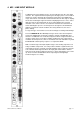
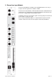
4.1 Input Select Switch
The SX-ST / SX-VT provides with two different connections type per input: one is on a conventional XLR-3F
receptacle and the “B” input on a multi-lines 25pin Sub-D connector. This is useful when different sources are
frequently swapped ( e.g. a set of microphones and a multi-track recorder/player ) or when a set of microphones
are connected using a stage box and a multi-ways cable
Position XLR: the XLR input is selected
Position IN B: the 25pin Sub-D connector is selected
NOTE
: The 25pin Sub-D connector is NOT a Line level input only, it provides with the same facilities as on
the XLR’s like phantom power and phase reverse. The wiring conforms with most popular equipments to
allow the use of “standard” ready made multi-ways cables - see also section xxxx for pin assignment.
All XLR's are wired with pin#2 High ( 1 = Gnd / 2= High / 3 = Low )
4.2 Mic power switch
Used to turn ON or OFF the phantom power:
Position DYN: 48V phantom power is OFF – for use with dynamic mics or line
Position 48: 48V phantom power is ON – for use with condenser mics
WARNING: The 48V will be applied to either the XLR or the 25pin Sub-D according to the Input Select switch
position. Caution must be taken when equipments other than a condenser microphone is connected to the
25pin Sub-D.
NOTE: The SX-ST / SX-VT mixers do not provide with T12 and P12 voltage supply. Some 48V phantom to
T12 or P12 adapters are available on the market
4.3 ∅ Phase reversal switch
This switch reverses the phase of the input signal without affecting the microphone powering.
It reverses the phase of any audio signal connected to the either the XLR or the 25p Sub-D connector.
4.4 Gain Controls
The primary input stage allows a wide range of gain setting, from - 20 dB up to +80 dB.
The rotary switch is used to set a primary fixed gain of: 0, 12, 24, 36, 48 or 60 dB.
Then, the rotary potentiometer ( also called TRIM ) is used for a progressive and fine adjustment of the input
gain, within a range of -20dB to +20 dB from the centre CAL position.
An additional +12dB or +24dB of gain is available on the linear Fader ( see also section 4.11.1 )
NOTE
: Gain controls should be used with care since the adjustment range is extensive. Check input level
using the LED’s Pre-Fader Level Meter and/or activate the PFL mode to avoid an overload or a weak signal
level. A signal level set too high can causes distortions and will leave you with less headroom, a level sets
too low causes a bad signal to noise ratio.