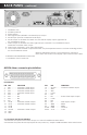
Model #: CVDVR900 MPEG-4 Embedded DVR User Manual now you can see www.svat.
INSTALLATION GUIDELINE A. Installation Environment In order to ensure the safety with the DVR product and maximize product performance, please notice the following while/ before you install the product: i. Only use with AV220V voltage supply, please check with the power supply with correct voltage before installation. DO NOT USE WITH ANY OTHER ADAPTER (DO NOT PLUG INTO AC380V HIGH VOLTAGE SUPPLY!) ii. Away from a humid place or exposure with rain. iii. DVR should be installin in a horizontal position. iv.
PRODUCT FUNCTIONS/ FEATURES • High speed embedded CPS and real time embedded control operation system are adapted with the product. It provides operation stability, no hang-up error, more reliability and ease for maintainance. • Operation with front panel and remote control, menu language also available in English/Chinese/Simplified Chinese. Security with double password lock. System management requires authority code in order to provide safety system.
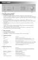
FRONT PANEL Front Panel and key definition: 1. LED Indicator status area • [1-8]LED Indicators: indicate 8 different channels for recording status, (for the 4-channel model: only works for LED[1-4], others will be off). LEDs that are on indicate recording in progress, and LEDs that are off indicate that the system is in standby. • [1-4]HD: indicate 4 different hard disk working status. LEDs that are on indicate hard disk work in progress, and LED off indicate that the hard disk is in standby.
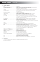
FRONT PANEL 5. ...continued Other options Key . . . . . . . . . . . . . . . . . . . . . . . . . . . . .Definition [Power ON /Power Off] . . . . . . . . . . . .System turn on and off(Stand-by and start) [Login/Locked]Key . . . . . . . . . . . . . . . .Login to enter to operate mode with require password and lock current setting activation [Status] . . . . . . . . . . . . . . . . . . . . . . . . . .Checking with record information store inside of hard drive. [Display Swap] . . . . . . . . . . . . . . . . .
BACK PANEL ...
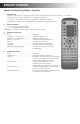
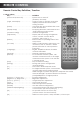
REMOTE CONTROL Remote Control Key Definition / Function: 1. Numeric Key [0-9]Keys : Numeric, for number key-in or video swapping. For non-menu screen, 1, 2, 3 and 4 represent for the video channel 1, 2, 3 and 4 respectively. [+], [-]Keys : Use for volume control, or while checking can play as next/pervious page, even changing some parameters for configuration. 2. Menu Operation : Up, Down directional keys; : Left, Right directional keys; [ENTER]Key: Confirm OR Time display while in monitor mode; 3.
REMOTE CONTROL Remote Control Key Definition / Function: 5. Other options Key . . . . . . . . . . . . . . . . . . . . . . . . . . . . .Definition [Power ON /Power Off] . . . . . . . . . . . .System turn on and off (Stand-by and start) [Login /Locked]Key . . . . . . . . . . . . . . .Login to enter to operate mode with require password and lock current setting activate [Status] . . . . . . . . . . . . . . . . . . . . . . . . . .Checking with record information store inside of hard drive [Display Swap] . . . .
SYSTEM START-UP/SHUT DOWN 1. System Start up Plug in your AC power, turn on the main unit, the red light will turn on while the system boots up. The system will be in standby mode. Press the [ON/OFF]button in front panel or remote control, the red light will turn off, then the monitor will be activated to show as 4-channel windows status. There will be channel numbers shown to indicate each input signal.
OPERATION INSTRUCTION A. Menu Setup While system is powered up, select [General Setting] to alter the system setup. The setup menu can be seen below, highlight the item for selection and then press [Enter] to confirm.
OPERATION INSTRUCTION Example: below is the record default setting: Record Settings Channel Quality Definition Frame Mode 1 14 CIF 25 CBR 2 02 CIF 25 CBR 3 03 CIF 25 CBR 4 04 CIF 25 CBR HDD Store Mode Centralize Individual Compound Return A-2 Record Parameter Setup: While system operated, select "Record Setting" to changing some setting in here: GENERAL SETTINGS Record Settings Timer Record Motion Detection Alarm Record Channels Housings Network Language Exit Record Settings Channel Quality Definition Fra
OPERATION INSTRUCTION continued Conversion Table for Image Quality and Encoding Rate Image Quality (Encode Rate Kbit/Second) Sharpness Encode Method CBR 1 2 3 4 5 6 7 8 D1 HD1 Fixed Fixed 2400 1200 2200 1100 2000 1000 1800 900 1600 800 1200 600 1000 500 800 400 CIF Fixed MAX 900 2400 800 2200 700 2000 600 1800 500 1600 400 1200 300 1000 200 800 D1 VBR MIN 2000 1800 1400 1200 1000 800 600 400 HD1 MAX MIN 1200 900 1100 800 1000 700 900 600 800 500 600 400 500
OPERATION INSTRUCTION continued • Date: Select either "Everyday", "Sun", "Mon", "Tue", "Wed", "Thu", "Fri", "Sat" and "Peak", when "Peak" time selected, the device will not use the stand-by function. • Period 1 and Period 2: Select start time and end time. Motion Mode: "On, Off" are the 2 different status settings to enable and disable this function respectively. Using the cursor to select and press [Enter] to confirm this function.
OPERATION INSTRUCTION A-5 continued Alarm Record Setting: Highlight and select Alarm Record, then press [Enter] for this selection, the sub-menu will shown (as below), then select the required area.
OPERATION INSTRUCTION continued Multi_Ch_Rec: "On, Off" are the 2 different status settings available. Use the cursor to select and press [Enter] to confirm this function.
OPERATION INSTRUCTION continued • Use the directional key to move small yellow block selection. When 4 points of yellow block are produced there will be q region wet up for the coverage setting area. Time insert: "On, Off" are the 2 different status settings. Use the cursor to select and press [Enter] to confirm this function. While "On" selected, a system clock will be shown while recording.
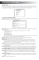
OPERATION INSTRUCTION A-10 continued Exit: Highlight and select Exit, then press [Enter] to confirm for save the change of setting then return back to main menu. B. Info Menu While system is in use, select [Info Menu] to check the menu content. The info menu can be seen as shown below, highlight the item for selection and then press [Enter]to confirm.
OPERATION INSTRUCTION continued Press [Enter] to see the recording video/audio signal, press [F1]for time select playback, and press [SLOW] for slow motion playback at a different speed. Press [FF]for fast forward playback and [FB]for fast backward playback, press [PAUSE] key to pause the video. [RETURN] to exit the playback window and back to main menu. B-2 Alarm Record: Highlight and select Alarm Record, then press [Enter] for this selection, the sub-menu will be displayed (as below.
OPERATION INSTRUCTION continued B-3 Alarm Log: Highlight and select Alarm Log, then press [Enter] for this selection, the sub-menu will be shown (as below), this allows you to see the recent alarm status and report.
OPERATION INSTRUCTION continued B-7 Machine Info: Highlight and select Machine Info, then press [Enter] for this selection, the sub-menu will be shown (as below), this allow to show all the machine ID number and software version. Info Menu All Alarm Alarm Operate Channel HDD Machine Machine Info Record Record Log Log Status Status Info Unit ID.
CF OPERATION INSTRUCTION continued 1. No Record will be shown if there is no data in the Compact Flash Card. 2. There will be a record list to viewed for data from the Compact Flash Card (as shown below). 3. Pressing [Enter] button for selected record data to playback, and press the [ESC] button to stop the playback.
RECORDING AND PLAYBACK INSTRUCTION D-1 Recording Manual Recording: 1. Use the [Record] button to start recording, will be a red dot on the top right side corner of the monitor which indicates the recording is in progress. 2. Press the [Stop] button to stop the recording and the red dot will turn off. Timer Recording: Refer to section A-3 Remark: The Channel 1 timer setting has the "Peak" time setting (from number 16 option), the peak setting is not available for other channel.
ADJUSTMENT FOR PICTURE PARAMETER AND SOUND LEVEL E-1 Parameter adjustment 1. Use the [Adjust] button to adjust brightness, color, contrast and the motion detect sensitivity level. 2. Use the [+] or [-] button for adjustment up and down. 3. Returns to menu after 5 seconds idle time without any adjustment. TECHNICAL SPECIFICATION DATA E-1 Parameter adjustment 1. Use the [Adjust] button to adjust brightness, color, contrast and the motion detect sensitivity level. 2.
TECHNICAL SPECIFICATION DATA Pow er Consumption Working Temperature Others AC 220V±20%, 50Hz±2% 15W( excluding w ith hard disk) 0~50 Working Humidity =80% Outer Dimension 2U Standard device box 440( W) ×90( H) ×420( D) mm Weight Clock 5.5KG( Excluding hard disk) Build-in system clock and calendar APPENDIX I-1 IDE requirement: 1. 2. 3. 4. 5. There are 2 IDE ports in the main board: 1 is master and 1 is slave. J4 IDE (the one close with power port) as master IDE port. J10 IDE as slave IDE port.