TABLE OF CONTENTS INTRODUCTION......................................................................................7 WHAT IS INCLUDED ................................................................................8 FEATURES..............................................................................................8 ADDITIONAL ACCESSORIES..................................................................... 10 BUTTONS & CONNECTIONS ....................................................................
TABLE OF CONTENTS...continued PTZ SETUP.................................................................................................20 PTZ controls.............................................................................................................. 21 MOTION DETECTION....................................................................................21 Setting Motion.......................................................................................................... 22 Motion Detect......
TABLE OF CONTENTS...continued Key Board Lock.......................................................................................................... 40 ID Number................................................................................................................ 40 Display Setup............................................................................................................ 40 Language....................................................................................................
TABLE OF CONTENTS...continued NETWORK VIEWING AND PLAYBACK........................................................ 56 SOFTWARE................................................................................................56 Online Software Icons................................................................................................ 56 Time Point Backup.................................................................................................... 58 Record.......................................
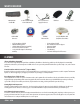
WHAT IS INCLUDED 16CH DVR with 500 GB HDD 10 RCA to BNC Connectors • • • • • 8 Indoor/Outdoor Night Vision CCD Cameras 2 x Four to One Power Supply for Cameras Software CD 10ft RJ45 Ethernet Cable 10 ft Power Adapter for DVR 4 Window Warning Stickers 1 CR2025 Battery for Remote (installed) 4 x 60 ft.
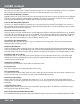
FEATURES..Continued Stay Notified with Email Alerts This system keeps you notified of events occurring in your monitoring location. You can set the unit to automatically send alerts to your email inbox whenever motion is detected or when cameras lose power. Up to seven different email addresses can receive these alerts. 8 Professional Grade Weatherproof Cameras Eight high resolution color cameras provide you with a clear and consistent picture at 420 TV lines of resolution.
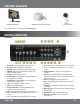
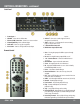
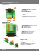
ADDITIONAL ACCESSORIES • CLEARVU7 (LCD Monitor) • CVW62 (60 ft. Camera Extension Cable) • VU301-C (Camera) For more information or accessories please visit: www.svat.com BUTTONS & CONNECTIONS Front Panel 1. 2. 3. 4. 5. 6. 7. 8. 9. 10. 11. 12. 13. Power LED – Indicates the DVR is properly powered on Rec LED – Indicates the DVR is in Recording mode Play LED – Indicates the DVR is currently in Playback mode HDD LED – Indicates there is harddrive activity.
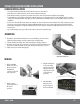
BUTTONS & CONNECTIONS...continued Back Panel 1. 2. 3. 4. 5. 6. Power Input– 12V 4. 16A VGA OUT – Connection to a VGA monitor Ethernet (LAN) connection – Connect to a router or modem Alarm Input/Relay - Connects Alarm adapter Audio Out - Connect to a speaker or amplifier RS-232/485 – Connects a PTZ (pan/tilt/zoom) adapter 7. Video Input – CH 1 to 16 – Camera connections 8. Audio In – Connects to an audio supported camera/ microphone (not included) 9.
BUTTONS & CONNECTIONS...continued PTZ CONNECTION 9 PIN D-SUB adapter for PTZ cameras: 1. 9 PIN D-SUB MALE Connection - Connects into RS 232/485 Port on the back of DVR 2. Connection for a RS 232 PTZ Camera 3. Connection for a RS 485 PTZ Camera - Using the “T” and “R” connections 4. Connection for a RS485 PTZ Camera - Using the “D+” and “D-” connections For more information on how to setup and use the PTZ camera with the DVR please see PTZ Setup.
THINGS TO CONSIDER BEFORE INSTALLATION CAMERA INSTALLATION • • • • The camera should be installed between 8 and 13ft above the area to be monitored Ensure there are no obstructions in the camera’s view, to maximize viewing area Ensure that the sunshade is positioned to avoid glare and position camera away from direct sunlight or indoor lighting Decide whether the camera will be wall-mounted, ceiling mounted or sit on a desk/table top.
CAMERA INSTALLATION...continued 5. Connect the male RCA plug from the 60 ft cable to the BNC to RCA connector. 6. Repeat the above steps for all of the included cameras. Note: For detailed instructions and information on the cameras included with this system, please refer to the Camera specifications on Pg. 63. CONNECTING ADDITIONAL DEVICES TO THE DVR This DVR has multiple connections which allow you to integrate additional SVAT or third party devices to the system.
CONNECTING ADDITIONAL DEVICES TO THE DVR...continued CONNECTING A MONITOR TO THE DVR (RCA COMPOSITE) 1. Connect a BNC to RCA connector to the MONITOR OUT connection on the back of the DVR. 2. Plug the RCA cable into the BNC connector. 3. Attach the other end of the RCA cable to a yellow RCA video input on your monitor. 4. Switch the TV/Monitor source to view the DVR. Note: If the monitor has multiple video inputs then the video source will need to be switched to watch the DVR.
CONNECTING ADDITIONAL DEVICES TO THE DVR...continued CONNECTING YOUR DVR TO THE ROUTER 1. Power off the DVR by removing the power cable from the back of the DVR. 2. Connect the included network cable to the back of the DVR in the “Ethernet” port (LAN). 3. Connect the other end of the network cable to an available port on the router. The ports should be labeled 1-4, or 1-8. 4. Power on the DVR by reconnecting the power cable on the back of the DVR.
GETTING STARTED Now that you have powered up the DVR and properly connected to a TV or monitor you are ready to begin using and customizing the DVR for your specific needs. The DVR will automatically begin recording once it has been powered on and initialized. Initializing the DVR is the normal start up process and can take a few moments. Using the Mouse • The included USB mouse makes using the CV501 - 16CH simple and efficient.
MAIN MENU The main menu consists of nine options: 1. Camera Setup 2. Motion Setup 3. Record Setup 4. Alarm Setup 5. HDD Management 6. Network Setup 7. Backup Setup 8. System Setup 9. Exit MAIN MENU As you navigate through the Menu of the DVR, you will notice that most fields are adjustable. If the Menu setting has to the right of it, you can adjust the value by either using the left and right directional buttons, or scrolling up or down with the mouse wheel.
MAIN MENU...continued Camera setup allows you to make adjustments to your cameras individually. A description of the adjustable fields will be found below. CAMERA 1. To choose which camera you want to work with highlight CAMERA so that the background is yellow and use the mouse wheel or directional keys to scroll to the camera you wish to adjust.
MAIN MENU...continued DISPLAY You can choose whether or not to display any individual camera. By setting the display to OFF the camera will not be displayed in live viewing, however the camera channel will continue to record as per the defined recording settings. The video will be displayed during playback. DWELL TIME Dwell time refers to the amount of time the footage from a particular camera will be displayed when you’re in auto sequence mode. You can set the dwell time for each camera individually.
MAIN MENU...continued PTZ Control from Live Viewing Mode To access the PTZ controls of the DVR you will need to use the mouse. 1. Move the mouse cursor to the bottom the screen for Pop Up Menu Bar to display. 2. Select the icon. The PTZ controls look like this: Note: To exit the PTZ control center, right click the mouse.
MAIN MENU...continued TO SET MOTION DETECTION 1. Select the camera you wish to configure the motion detection for. 2. Use the mouse wheel, or the directional arrow buttons to toggle between ON and OFF. MOTION DETECT Motion detection can be set to ON or OFF. When set to ON, the DVR will recognize and perform specific activities when motion is detected based on your settings. BUZZER The Buzzer can be set to ON or OFF.
MAIN MENU...continued RECORDING SETUP 1. Access the Main Menu. 2. Select the Record Setup icon. RESOLUTION You can set the resolution to: NTSC Mode 1. 720 x 240 (max 60 PPS) 2. 360 x 240 (max 120 PPS) PAL Mode 1. 720 x 288 (max 50 PPS) 2. 360 x 288 (max 60 PPS) Note: NTSC is the video standard for North America. Europe and other countries use the PAL video standard. NTSC videos or cameras will not work on PAL television sets or monitors. Changing the resolution will affect the picture quality.
MAIN MENU...continued ALARM RECORD PPS You can change the PPS for alarm record. You may wish to change the alarm PPS so that there is a higher PPS for when an alarm (e.g. motion) is detected by the DVR and a lower PPS for Normal Record. To Change the Alarm Record PPS: 1. 2. 3. 4. Select to adjust the Alarm Record PPS. Use the mouse wheel or the directional buttons to adjust the PPS, the most PPS per camera is 30 PPS.
MAIN MENU...continued RECORD QUALITY There are four levels of record quality you can choose from, and it is adjustable per camera if recording with 720 x 240 resolution. If using 360 x 240 resolution, cameras are adjusted in pairs (1 & 2, 3 & 4, 5 & 6 etc...): 1. 2. 3. 4. Low Medium High Best To Change the Record Quality: 1. 2. 3. 4. Highlight the record quality option and click to change the record quality. Use the mouse wheel or directional keys to change the cameras record quality setting.
MAIN MENU...continued AUDIO RECORD The DVR is capable of recording one channel of audio. You can connect a camera that has a built in microphone or connect an external microphone into the RCA audio input to configure the DVR to record with audio.. The cameras that are included with the DVR do not support audio. To record with audio: 1. 2. 3. 4. Highlight the Audio Record option. Use the mouse wheel or directional keys to change from OFF to ON. Press ENTER or Click the to save changes.
MAIN MENU...continued To set the schedules: 1. Highlight SCHEDULE SETUP and select to enter the schedule record Menu. 2. Select the type of recording you wish to use (Full, Alarm, No) from the bottom of the Menu screen or use the fast forward button to toggle between the type of recording. 3. In the calendar display, press ENTER or click on the hour and day you wish this method of recording to happen. to save changes and return to the Record Setup Menu. 4. Select the 5.
MAIN MENU...continued External Alarm Mode You can adjust your external alarm for Normally Open (NO), or Normally Closed (NC). Please consult the external alarm manufacturer for details regarding whether to set up the External Alarm Mode to Normally Open or Normally Closed. 1. Use the mouse wheel or directional buttons to change from Normally Open (NO), or Normally Closed (NC). 2. Press Menu or select the to return to the Menu. 3. Press Menu or select the to exit the Main Menu and save your settings.
MAIN MENU...continued The event log setup allows you to choose which alarm triggers will be saved to your event log (maximum 3000 events). Setting up the event log allows you to start playing recorded footage by specific events so that you do not have to fast forward through long periods of footage to see when the alarm is detected. It also serves as a list with the important events that have occurred, so that you can easily trace them, and when they happened. To Setup the Event Log: 1. 2. 3. 4. 5. 6.
MAIN MENU...continued To Setup the Relay Time Setup: 1. 2. 3. 4. Select RELAY TIME SETUP from the Alarm Setup Menu. Select to access the Relay Time Setup Menu. Highlight the type of alarm you want to set up. Use the mouse wheel or directional keys to change the length of time. The 12V signal will be sent to your external alarm when an alarm is detected. 5. Press Menu or select the to return to the Main Menu or press the Menu button. 6.
MAIN MENU...continued HDD INFORMATION This option will allow you to view the total capacity of the connected hard drive as well as the percentage of remaining space. This Menu is only used to display your HDD status, and no settings can be adjusted on this screen.
MAIN MENU...continued To Format the HDD: 1. 2. 3. 4. 5. 6. Select HDD FORMAT SETUP. to enter the HDD Format Setup Menu. Select Use the mouse wheel or directional keys to change from DISABLE to ENABLE. Select to format your HDD. You will be prompted to ensure that you really want to format the hard drive. Select YES to format the hard drive, or NO to exit the Menu and not delete the stored footage. The selected button will looked as if it is pressed in. 7.
NETWORK SETUP...continued To Change from Static to DHCP Addresses: 1. Under IP Mode, use the mouse wheel or directional keys to change from DHCP to STATIC. 2. Press Menu or select the to exit the Network Setup Menu or press the Menu button. 3. Press Menu or select the to exit the Main Menu and save your settings. The DVR may take a few moments to load the settings. HTTP Port: Refers to the port that your DVR will use to communicate with your network and the Internet.
NETWORK SETUP...continued DDNS: (Dynamic Domain Name Service) This Menu option allows you to set up a common name for the DVR instead of an IP address. This feature is used if you have a Dynamic IP address from your ISP and the IP address is constantly changing. To Setup your DDNS: 1. Select to setup the DDNS. 2. Highlight DDNS Setting. Use the mouse wheel or directional keys to change from DISABLE to ENABLE. 3. Highlight PROVIDER. Choose your DDNS provider from the list. 4. Highlight HOST NAME.
NETWORK SETUP...continued The virtual keyboard will appear for you to insert the following information: Motion Setting: Enables the DVR to send you an email when motion is detected by one of the cameras. Alarm Setting: Enables the DVR to send you an email when an external alarm is triggered by one of the attached devices. Mail Server: Set your SMTP mail server address. This is going to be provided by your email service provider. For example: Google GMAIL: smtp.gmail.com Yahoo! Email : smtp.mail.yahoo.
NETWORK SETUP...continued 5. After you have entered all the information select the button to save changes and exit the menu. The DVR may take a few moments to load.
BACKUP SETUP The DVR allows you to backup your recorded footage onto a separate and portable USB flash drive as well as a CD/DVD. USB BACKUP To Setup Backup Recording: 1. Insert your USB flash drive into the USB port on front of the DVR. 2. Access the Main Menu by clicking Menu or move the mouse to the bottom of the screen to reveal the pop up bar. 3. Select the Main Menu icon. 4. In the Main Menu, select Backup set icon.
BACKUP SETUP...continued 2. Choose the starting date and time of when to transfer the video footage. Highlight the value you wish to change and use the directional keys up and down or the mouse scroll wheel to adjust the value. 3. Choose the ending date and time of when to end the transfer of video footage. Highlight the value you wish to change and use the directional keys up and down or the mouse scroll wheel to adjust the value.
BACKUP SETUP...continued To Backup Saved Video Footage with CD/DVD burner: 1. Power on your external CD/DVD burner according to the manufacturers directions. 2. Plug the external CD/DVD burner into the DVR through the left USB connection on the front of your DVR. 3. Power cycle the DVR by disconnecting and re-connecting the power cable. Allow system to start up and detect all connected devices. . 4. Select the main menu icon . 5. In the main menu, select Backup set icon 6.
SYSTEM SETUP...continued 4. NTP (Network Time Protocol) Mode can be enabled or disabled to allow the DVR to synchronize the date and time with a NTP server. By default the NTP server IP is set to 198.123.30.132. 5. Choose your GMT Time zone. Example: Central Time Zone = -06:00 GMT. 6. Update Time will be how often the DVR checks with the NTP server to update the system time with the current NTP server time. It can be set from every 1 hour up to every 24 hours. 7.
SYSTEM SETUP...continued LANGUAGE This DVR allows for the following 13 languages: English, Chinese, Italian, French, Japanese, Spanish, Polish, simplified Chinese, Greek, Hungarian, Dutch, Russian and Czech To change the on screen display language: 1. Highlight LANGUAGE. 2. Use the mouse scroll wheel or directional keys to change to your desired language. 3. Press Menu or select the to save and exit. 4. Press Menu or click to exit the Main Menu and save these settings.
SYSTEM SETUP...continued 4. Use the directional keys or the mouse to select either YES or NO. Select YES to load the factory default settings. to save settings and return to System Set. 5. Click to save settings and return to Main Menu. 6. Click Load Setup From USB This option can only be used if the DVR settings have been previously backed up to USB. The DVR settings will be saved on the USB drive as DVR.cfg. Backup Setup to USB This will save the current DVR settings to a USB flash drive.
LIVE VIEWING POP UP MENU BAR (operation) – Using the USB Mouse, the pop up menu bar allows you to view the following options. PTZ control – Please refer to the PTZ control section. HDD & USB INFORMATION You can quickly access your HDD & USB information right from the Pop Up Menu on the live viewing screen. This will let you easily determine how much space is left on your HDD and your USB drive.
PLAYBACK By clicking the Play button from the Pop Up Menu, front panel, or remote control a Play Search window will pop up. The CV501 - 16CH allows you to review your playback with two different search options: 1. Play Time Search – Allows you to view your recorded footage based on the day and time you wish to preview. This option works best when you know the approximate time/day that you want to view footage from. 2. Event List Search – Calls up an event list with many different types of events.
PLAYBACK...continued SEARCH BY TIME 1. Select the play button to call up the playback Menu on the front of the DVR or the remote. or press PLAY 2. Highlight PLAY TIME SEARCH and select using the mouse or by pressing enter on the DVR or remote. 3. Use the mouse wheel or directional keys to choose the date and time you wish to view. 4. The total time you have been recording for is listed at the bottom of the play time search.
PLAYBACK...continued BACKUP VIDEO PLAYBACK Once you have backup footage on your USB drive, you can archive that footage or view it on a computer. How to View Backup Footage from USB: 1. 2. 3. 4. 5. Insert your USB drive into your Windows based PC or laptop. Install the viewer application by opening R6VIEWER.EXE. Use overlay mode when prompted. Click "Open" under File Select. Navigate the USB drive and select the *.264 file you wish to view.
PLAYBACK...continued To begin viewing playback click the play button. BACKUP PLAYER – PLAYBACK CONTROL The playback buttons are as follows from left to right: STEP BACK: REWIND: PAUSE: STOP: PLAY: FAST FORWARD: STEP FORWARD: Pauses playback and reverses playback one frame each time it is clicked Rewinds playback Pauses playback Stops playback Begins playback Fast forwards playback Pauses playback and advances footage one frame each time it is clicked.
NETWORK GUIDE REQUIREMENTS You will need to have: • The DVR connected to a router • The router connected to the Internet • A PC or laptop that is connected to the same router that the DVR is connected to. The PC can be connected by a wired or wireless connection • Internet Explorer 6.0 or greater (to check the version of Internet explorer open I.E. In the top Menu bar select “Help” and then select About Internet Explorer. The version of I.E. will be displayed.
NETWORK GUIDE...continued Method 1 (Recommended): Add the DVR’s IP address to the Trusted Sites in Internet Explorer. 1. Open up Internet Explorer. 2. Click on TOOLS. 3. Click on INTERNET OPTIONS. 4. Click on the SECURITY Tab. 5. Click on TRUSTED SITES. 6. Click on the SITES button. 7. Type in the IP address of the DVR in the following format: http://192.168.0.108 and click ADD. 8. If Require server verification (https:) for all sites ...” is selected you will need to uncheck the selection box.
NETWORK GUIDE...continued Method 2: 1. Open up Internet Explorer. 2. Click on TOOLS. 3. Click on INTERNET OPTIONS. 4. Click on the SECURITY Tab then the CUSTOM LEVEL button. 5. Change the ActiveX settings listed below.
NETWORK GUIDE...continued Log in to the DVR (Using Internet Explorer): By default the DVR will require a user to input a username and password before being able to view the DVR online. The default username and password for the web interface of the DVR is: Username: admin Password: admin To add a new user or enable Anonymous Login see User Management. Installing the ActiveX controls: There will be a yellow information bar that pops up below the address bar in Internet Explorer.
NETWORK GUIDE...continued VIEWING YOUR DVR OUTSIDE OF YOUR NETWORK Now that you have successfully viewed your DVR and cameras from a computer it is time to set up your router to view the DVR while at a remote location. This process is called Port Forwarding and you can find detailed instructions on how to complete the required steps at http://www.portforward.com. *Port forwarding is required if you want to view the DVR from a computer that is not connected to the same router.
NETWORK GUIDE...continued TESTING Now that you know your external IP address, you can perform a test to ensure your DVR is accessible from outside your network (over the internet). This test should be performed by a computer that is not on the same network as the DVR. Although, using the external IP on the same network will sometimes work, it will not work in all cases and it is best to test from a remote location. 1.
NETWORK GUIDE...continued To Configure the DVR to Work with DDNS: 1. Press Menu and select NETWORK SETUP. Insert password if required. The default password is “1111”. 2. Navigate to DDNS and press ENTER. 3. Change DDNS SETTING to ENABLE. DDNS (Dynamic DNS) Instead of having to type in the IP address to access the DVR online you can use DDNS to create a easy to remember website name to access the DVR. The DVR has many DDNS Provider web addresses built into it. The following instructions are for DYNDNS.
NETWORK GUIDE...continued DYNDNS.ORG ACCOUNT SETUP (required if using DYNDNS.ORG) 1. Open Internet Explorer and type http://www.dyndns.org in the address bar. 2. Create a new account by clicking the “Create Account” link in the top right hand corner of the site. 3. Enter your preferred user name, email address, and password. 4. Optional information can be left blank, unless you would like to enter it. 5. Read and agree to the Acceptable Use Policy (AUP) by checking the box and click “Create Account”.
NETWORK VIEWING & PLAYBACK Once you have your DVR set to view online, the software to view the footage differs from the software that is in the DVR. Please refer to the following instructions when viewing live footage online. This is what the online viewing software will look like: 1. DVR Configuration: When you click DVR configuration, it displays a Menu for you to change/review settings. 2. Online Visitors: Displays how many visitors are viewing your camera system. The maximum connected is 4. 3.
NETWORK VIEWING & PLAYBACK...continued 6. Rec: This will record the footage that is currently being displayed onto the desired save location on your computer. This will work in live mode or in playback mode. Press STOP to terminate the recording and view the saved footage. It will be saved in H.264 format and will require the player to view the recorded footage. 7. Full: Switch to full screen mode.
NETWORK VIEWING & PLAYBACK...continued ADDITIONAL OPTIONS: You can left click the mouse on the viewing windows to call up additional options. The extra options are described below: Snapshot: Will allow you to save a single picture from the image. Performance: You can select the image quality (high, medium, & low). Use Overlay: Choosing this option allows you to speed up video display and reduce CPU loading time. Play Audio: You can play audio by channel. (Note: The included cameras do not support audio).
NETWORK VIEWING & PLAYBACK...continued DVR CONFIGURATION OPTIONS SYSTEM OPTIONS The system information, network information and other options are displayed when this option is clicked. System Information Server Name: This is the name of your DVR. It will be displayed in the title of the web browser and can be used to distinguish your DVR from another. MAC Address: The MAC address is the physical address of the network card that is installed in the DVR.
NETWORK VIEWING & PLAYBACK...continued Load Default Load Setup From Default (Setting): Applies factory default settings. You will be prompted to confirm the restore. Load Setup From: (Browse): Browse to the location where the system configuration settings are stored. Load Setup From: (Setting): Applies the configuration settings from the backup file. Backup Setup (Download): Prompts you to save the current configuration settings to your computer.
NETWORK VIEWING & PLAYBACK...continued DDNS Enabled/Disabled: This will enable the DVR to connect to the DDNS provider listed below. If disabled the DVR will not update the DDNS website with the current information. Provider: Choose the DDNS service provider for the DVR to connect to. See DDNS SETUP for more information on the service providers. Hostname: This is the hostname set up for your DVR. Used to connect to your DVR through a web browser.
NETWORK VIEWING & PLAYBACK...continued FTP Server: Enter the Hostname or IP address of the FTP server. Username: A username that has the proper permissions on the FTP server to create directories and add files. Password: Enter the password for the username listed above. Port: Enter the port the FTP server uses. The default port for FTP sites is 21. Path: Enter the path to save the H.264 format video files. Apply: Saves your Mail and FTP settings.
3G MOBILE DEVICE PORT FORWARDING...continued From Your Mobile Device: • Open up the web browser application • Click Options and choose the option that will allow you to type in a URL • Type in rtsp://74.11.213.177/CH03 This will pull up channel 3 of your DVR if port forwarding settings are set up correctly and your phone is compatible with this DVR.
3G MOBILE DEVICE PORT FORWARDING...continued If additional port forwarding steps are required, contact your ISP (Internet service Provider) to assist with bridging the modem and router together. • Check all of your network connections and go through the above steps again to make sure a configuration error was not made • You may have to configure PPPoE settings to match the settings provided to you by your Internet Service Provider (ISP).
MOBILE VIEWING INSTALLATION GUIDE...continued Sony Ericsson K608i The first step is to copy the MobileViewer.jar file to a storage location on your mobile that can be accessed using the file manager on the mobile device. 1. Copy the MobileViewer.jar file from the CD or website onto the desktop. 2. Connect the mobile device to your PC to download the mobile software. • Open up My Computer.
MOBILE VIEWING INSTALLATION GUIDE...continued Name: This is arbitrary and can be named to your liking. Host: This is the IP address for your DVR. If connecting using the 3G or other wireless network, the proper ports must be forwarded on your router. See Port Forwarding for instructions. Ex. Host: 74.11.213.177. Port: This is the http port used by the DVR. By default the port is 80. User: The user account used to access the DVR. By default the user is “admin”.
MOBILE VIEWING INSTALLATION GUIDE...continued iPhone and iTouch Viewing (Safari) Be sure that the mobile device that is connected can connect to the internet via cell phone network or Wi-Fi. If connected to the same Wi-Fi network as the DVR the iPhone can access the DVR cameras via the LAN (internal) IP address or the WAN (external) IP address. 1. Open up Safari on the iPhone or iTouch. 2. In the address bar type in: http://IPADDRESS/iphone.html. Ex. http://74.11.213.177/iphone.
MOBILE VIEWING INSTALLATION GUIDE...continued 2. On the BlackBerry: (Setting may not be available depending on cell phone service provider) • Open up the Menu • Open Options/Settings • Open Advanced Options • Click on TCP • You must set your APN settings according to your specific Cell Phone Service Provider. Contact your cell phone service provider for the APN, APN username, and APN password 3.
MOBILE VIEWING INSTALLATION GUIDE...continued The following will be displayed: Name: This is arbitrary and can be named to your liking. Host: This is the IP address for your DVR. If connecting using the 3G or other wireless network the proper ports must be forwarded on your router. See Port Forwarding for instructions. Ex. Host: 74.11.213.177. Port: This is the http port used by the DVR. By default the port is 80. User: The user account used to access the DVR. By default the user is “admin.
TROUBLESHOOTING GUIDE My DVR has no power • Check the power cord connection to the DVR and the outlet and ensure that the DVR has power There is no way to turn the DVR off • The DVR is set to run as long as it is plugged in, if you would like to turn it off you have to unplug it I cannot hear recorded audio when playing back • Are audio equipped cameras being used? Please note that audio equipped cameras are not included with this DVR system • Make sure that the audio cable is properly connected a
TROUBLESHOOTING GUIDE CONT...
TROUBLESHOOTING GUIDE CONT... My camera is being displayed in black and white • • Night vision mode displays in black and white. Make sure there is enough lighting in the room to check if color is working Power cycle the DVR by unplugging the DVR with a camera still connected. Leave for 10 seconds and pow on again.
DVR SPECIFICATIONS continued...
CAMERA SPECIFICATIONS CAMERA SPECIFICATIONS (MODEL#: VU301 - C ) Camera Type Image Sensor Resolution Outdoor Use IP Rating Focal Length Focus Type Optimal Focal Distance Night Vision Number of IR LEDs and Range IR LED Control Min.
CAMERA MANUAL VU301-C Camera 1. Sun Shield: 2. Infrared (IR): 3. 4. 5. 6. Helps prevent glare from bright lights LEDs Allows the camera to see in the dark up to 15ft away. CDS Sensor: Turns on the infrared LEDs when it gets dark Camera Housing: Made of anodized aluminum to prevent rust Camera Mount: Allows the camera to be desk or wall mountable 4 PIN DIN Female Connection IMPORTANT INFORMATION While this camera is weatherproof, it is not waterproof.
CAMERA DRILLING TEMPLATE To wall mount the camera, drill three holes using a 3/16" drill bit and the template below. Insert the supplied wall anchors into holes and secure camera to wall with supplied screws. DRILL HOLES IN THESE POSITIONS DRILL HOLES IN THESE POSITIONS DRILL HOLES IN THESE POSITIONS .......................................................................................................Tear Here..............................................................................................