SHE-7 K1 0370.24 MANUAL This device complies with Part 15 of the FCC Rules. Operation is subject to the following two conditions: (1) this device may not cause harmful interference, and (2) this device must accept any interference received, including interference that may cause undesired operation. SVS Nachrichtentechnik Gm Instructed 8 D798 Troubleshooting Yes +145 OFFER 99RB.
Caution: Please read attentively this manual. Damages caused by missus are not subject to warranty, The producer may not be responsible for further damages, caused indirectly by use of this equipment. All changes or modifications not expressly approved by the party responsible for compliance could void the user's authority to operate the equipment. 1. DESCRIPTION This receiver SHE-7 K1 is to function with the appropriate handheld transmitter SHY-7.
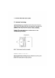
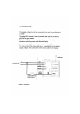
2. OPERATING INSTRUCTIONS 2.1 Individual Code Setting Open the housing by turning the 4 screws in the boll em left hand side. Take off the upper case. Now You may chose Your individual code by setting the 8 little switches which all have 3 different positions. That is why You have a choice of 6561 possibilities. Caution: The code setting has to be the same as in the corresponding transmitter. CODE SWITCH picture 1: top view opened / position of code switch 2.
switch No, functionality 1at Pos. "ON" The distribution 1 of the transmitter activates the relay contact. 2at Pos. "ON" ‘The push button Z of the transmitter activates the relay contact 3 at Pos "ON" ‘The prohibitionist 3 of the transmitter activates the relay contact. 4 at Pos. "ON" The push button 1 deactivates the relay contact before time out. Atropos.
the result that the relay switches off and after that the RF communication is recognized once again, and so on. 2.3 The Antenna The receiver SHE-7 K1 is equipped with a After installation the antenna should not be wounded around other cables or should not be hidden by metallic objects. After preparation of the receiver for Your application, please fix the PCB again and close the housing.
3. Connections The supply voltage has to be connected to the red and the black cable. The relays NO-contact is free of potential and may be connected with the two Grey cables. Take care of the maximum supply voltage as well as of the maximum switching power (see technical mandala. To switch on the NO-contact without the handheld RF transmitter You may connect the white cable by i.e. a distribution to the positive supply voltage.
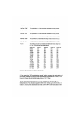
4. TECHNICAL DATA SHE-7 K1 frequency : 433,020 MHz 150kHz demodulation : fog. AM-demodulate supply voltage : 12 VDC (max. 30V) supply current with relay } output : potential free relay contact switching voltage : <42V nominal sw.