
Owner's Manual


INSTALLATION
SVS
CYLINDER
SUBWOOFERS
SVS
Cylinder
Subwoofers-
Base
Plate
Removed:
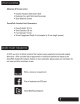
1.
Using
a
helper
as
needed,
lay
the
cylinder
subwoofer
sideways
on
a
stable
surface.
Take
care
to
avoid
damaging
the
ampl.ifier.
2.
Peel
off
the
original
equipment
{OE)
rubber
disc
feet.
3.
Remove
the
OE
machine
screws.
Support
the
base
plate
as
needed
to
prevent
it
from
inadvertently
dislodging
while
removing
the
screws.
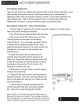
Important
Notice:
-
If
you
are
using
a
powered
bit
driver
to
remove
and/or
install
the
machine
screws,
avoid
excessive
downward
pressure
on
the
screw,
as
that
may
dislodge
the
t-nut
mounted
to
the
backside
of
the
woofer
end-cap
4.
Remove
the
base
plate
and
the
dowels
and
set
aside.
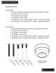
5.
Gather
all
of
the
51
mm
long
machine
screws
from
the
Isolation
System
kit.
There
are
two
{2)
thread
sizes
provided
-
~-20
and
M6.
6.
Compare
the
OE
feet
machine
screws
to
the
Isolation
System
51
mm
long
machine
screws
and
select
the
matching/correct
thread
size.
7.
Install
each
Isolation
foot
by
inserting
the
51
mm
long
machine
screw
through
the
bottom
opening
of
the
rubber
foot,
through
the
opening
in
the
steel
outer
shell
and
into
the
t-nut
on
the
backside
of
the
woofer
end-cap.
8.
Make
sure
the
machine
screw
is
correctly
aligned
and
does
not
cross-thread.
9.
Tighten
the
machine
screw
avoiding
excessive
downward
pressure.
Once
the
screw
fully
tightens
and
starts
to
pull
against
the
end-capt-nut,
tighten
securely
using
hand-pressure.
10.
Using
a
helper
{if
needed)
carefully
stand
the
cylinder
subwoofer
back
onto
the
installed
Isolation
feet.
Take
care
to
avoid
damaging
the
amplifier.
Important
Notice:
-
Do
not
drag
the
subwoofer
base
plate
across
the
flooring
with
the
Isolation
feet
installed.
This
may
damage
the
Isolation
feet
or
the
base
plate.
If
you
need
to
move
the
subwoofer,
always
lift
(use
a
helper
if
needed)
the
subwoofer
and
then
place
it
into
the
new
location.