DVR4/9-SecuraNet™ USER MANUAL SW242-4SN / SW242-9SN / SW243-4MB / SW243-9MB
Getting Started FCC WARNING STATEMENT This device complies with Part 15 of FCC Rules. Operation is subject to the following two conditions: (1) This device may not cause harmful interference, and (2) This device must accept any interference received, including interference that may cause undesired operation Important Notice All jurisdictions have specific laws and regulations regarding the use of cameras.
Contents Chapter 1: DVR Features ........................................................................................................................ 1 Chapter 2: DVR Layout ........................................................................................................................... 2 2.1 Front Panel ........................................................................................................................................ 2 2.2 Rear Panel.......................................
8.1 Playback Control ............................................................................................................................. 24 Chapter 9: USB Programming(optional)............................................................................................ 25 9.1 Client Program Installation............................................................................................................... 25 9.2 Program Interface...............................................................
1. DVR Features z 4-Channel: 4 BNC Camera Inputs - 2 BNC Video Outputs 9-Channel: 9 BNC Camera Inputs - 1 BNC Video Output z 4-Channel: 2 Audio Inputs - 2 Audio Outputs 9-Channel: 1 Audio input - 1 Audio Output z View and Operate over Network (Broadband Connection Required) z NTSC or PAL System z Motion Detection with Sensitivity and Area Settings z Timed Schedule, Alarm and Motion Triggered Recording Modes z Hard Disk Support up to 500GB z Built-in USB 2.
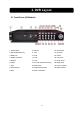
2. DVR Layout 2.1 Front Panel (All Models) 1. Power switch 10. Record 23. IR Receiver 2. Removable HDD Tray 11. CH1 24. Up Arrow 3. HDD Lock 12. CH2 25. Select 4. USB 2.0 Interface 13. CH3 26. Left Arrow 5. Rewind 14. CH4 27. Down Arrow 6. Pause 15-19. CH5-9 (9CH DVR Only) 28. Right Arrow 7. Play 20. Mute Audio 8. Fast Forward 21. Display All Cameras 29. Power Indicator 30. HDD Indicator 9. Stop 22.
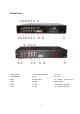
2.2 Rear Panel 1. Audio Input(s) 7. VGA Output (Optional) 13. CH6 2. Video Output(s) 8. LAN 14. CH5 3. CH4 9. Audio output 15. RS485 / Sensor Input / 4. CH3 10. CH9 Alarm Output 5. CH2 11. CH8 16. DC Power Input Jack 6. CH1 12. CH7 17.
2.
3. Hard Drive Installation WARNING: Do not remove Hard Drive while DVR is running Ensure HDD jumpers are set to MASTER prior to inserting drive SW243-4MB / SW243-9MB has a hard drive pre-installed, please skip this step. 3.
4.
5. Starting the DVR 5.1 Firmware Version After connecting the power adapter and turn on the power button, the system will boot-up and display the version and released date of the DVR’s current firmware. 5.2 Detecting Installed Hard Drive DVR will detect the installed hard drive and display the hard drive information. 5.3 Format Hard Drive When the DVR detects a new hard drive you will be prompted to format the hard drive before using the DVR Press [SEL] to format or press [MENU] to cancel.
6. DVR Menu System 6.1 Navigating the Menus [MENU]: enters Main Menu [▲, ▼, ◄ and ►]: move the cursor [SEL]: select/modify settings [MENU]: press again to exit or return to previous menu. 6.
6.3 Camera Setup Camera Setup allows you to turn cameras on or off. Press ▲, ▼, ◄ or ► button to select a channel and then press [SEL] to modify the setting ON or OFF. Note: If a camera channel is set to off it will not record (Refer to 6.4 Record Setup) 6.4 Record Setup Record Setup allows you to set up recording channels. Press ▲, ▼, ◄ or ► button to select a channel, and then press [SEL] to modify the setting to ON or OFF.
6.6 Video Quality Video Quality has 4 different settings: Highest, High, Normal and Low. The higher the video setting the better quality images, however higher quality images require more hard drive space. Press [SEL] to change the quality setting. 6.7 Record Schedule Setting the Record Schedule allows you to customize the type of recording depending on the time of day. The time line indicates 24 hours of a day based on AM/PM (0 = 12).
6.8 Sensor Setup Sensor Record Time indicates how long the recording time is when the motion or sensor is triggered. Alarm On Time indicates whether the buzzer will sound when motion is detected. CONT: Continuous alarm until any key is pressed. OFF: No alarm 6.9 H/W Sensor Setup Note: Sensors and extension alarms are not included with the DVR system and may be purchased separately. HARDWARE SENSOR SETUP: There are 3 different modes for sensor setting: NOT INSTALLED, NORMAL -CLOSE and NORMAL-OPEN.
Area Selection: Press ▲, ▼, ◄ or ► button to select a block, and press [SEL] button to set the block to detect motion, The area is detectable when it is clear, the area is not detectable when it is covert by shadow. 6.11 Hard Drive Setup This section will display the current hard drive status and usage options OVERWRITE ENABLED: ON: overwrite oldest video when hard drive is full. OFF: stop recording when hard drive is full.
Enter the current password first, and then enter six characters as your new password, repeat the new password to confirm. If you forget your password, please contact technical support for assistance. 6.13 Miscellaneous Setup - Set Time The system date and time format is YYYY/MM/DD and HH:MM: SS. Press ◄ or ► button to select the data to modify, press [SEL] to modify. Press [MENU] to save and return to previous menu. 6.
6.15 Miscellaneous Setup - Audio Port Setup For 4-channel DVR, there are 2 audio inputs. For 9-channel DVR, there is 1 audio input. You can select the audio recording function to ON or OFF, and select the video channel that you like to record the audio on. 6.16 Miscellaneous Setup - PTZ Setup SPEED: Set the baud rate (4800,9600, 19200,38400) match to your speed dome. PROTOCOL: Supports “PELCO-D” and “PELCO-P”. Select the protocol according to your speed dome’s protocol.
6.18 Miscellaneous Setup - Auto Sequence Auto sequence function allows you to view each active video channel in full screen mode and display alternately. Auto Sequence dwelling time can be also adjusted to 1, 2, 5, 10, 15, 30 or 60 seconds, or turn it off by choosing OFF. To activate Auto Sequence mode, press [ ] button during monitoring or recording mode. To exit auto sequence display, press [MENU] or any of channel selection buttons. 6.
CON: Contrast BRI: Brightness HUE: Hue SAT: Saturation Press ▲ or ▼ to select the item, and then press [SEL] to adjust the value. 6.21 Miscellaneous Setup - Password Enable The password will be required to control the DVR when this option is set to “ON”, and the password is not required when this option is set to “OFF”. 6.22 Miscellaneous Setup - VGA Setup Select a VGA resolution match to your CRT or LCD monitor.
6.23 Network Setup Network Setup allows you to prepare the DVR for viewing over the internet or local network. MAC ADDRESS: In a local area network(LAN), the MAC (Media Access Control) address is your computer’s unique hardware identity code.(On an Ethernet LAN,it is the same as your Ethernet address.) When you are connected to the Internet from your computer (or host as the Internet protocol thinks of it ),a corresponding table relates your IP address to your computer’s physical (MAC) address on the LAN.
SUBNET MASK: Subnet Mask is used to determine what subnet an IP address belongs to. A number that is used to identify a sub network so that IP addresses can be recognized on a local area network. Consult your modem/router for your LAN’s subnet mask. GATEWAY: Set this number to the gateway set by your modem/router. [NOTE] To adjustment the IP ADDRESS,SUBNET MASK and GATEWAY value, only when the [STATIC] mode is being selected. DNS ADDRESS: This code should be provided by your local ISP.
HTTP PORT: This port number is used to communicate with PC Client. The default value is 80. . USER SETUP: When accessing the DVR from a remote location you will be prompted for a login and password. The default is “admin” for full administrator rights. Set “User ID” and password to setup a user with limited rights to prevent tampering. DDNS SETUP:If you require an external service to maintain a dynamic IP address enter the user information here.
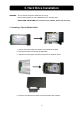
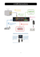
LAN-DVR Connection See the diagram below for steps to connect your DVR to a local area network or the internet. For remote monitoring from your computer,you must have a LAN connection available or broadband Internet access. You need to register a www.dyndns.org to get a free account .After registration,you will have a username and password. You can also register your domain name on the website. Please refer to Chapter 5,P. Network Setup for more details.
which supports USB Memory Stick device. If your DVR is with PC-link USB interface, please refer to this section. Move the cursor to “VIEW EVENTS”, press [SEL] to enter event list. Press ▲ or ▼ button to move the cursor, and then press [SEL] to select the event you like to backup and return to previous menu.
Insert your USB memory stick into DVR’s USB port. Move the cursor to “BACKUP TO USB DEVICE”, press [SEL] button. DVR will check your USB device and then start to copy the backup file. Please read Chapter 8 about how to play back your recorded video. 6.25 Reset Menu If you select this item, the system will restore all your settings to factory default values. You need to enter your password to reset the menu. Chapter 7: Record 7.
[●]: the red dot next to the channel name indicates that the channel is being recorded. [A-REC]: indicates the current record schedule is set to be NORMAL-RECORD mode. [S-REC]: indicates the current record schedule is set to be SENSOR-RECORD mode. [N-REC]: indicates the current record schedule is set to be NO-RECORD mode. [39%]: indicates the percentage of hard disk space used. 7.2 Audio Recording [ ]: indicates this video channel is bundled with an audio port, and the audio output is on.
High Normal Lower 90 110 123 125 153 171 188 229 256 375 458 513 4500 5500 6150 Unit: Hour User also can calculate and estimate record time by below formula 160G Byte @16 frames per second @Normal quality 160(Gbyte) × 1024 (Mbyte) × 1024 (Kbyte) 7 (Kbyte/frame) × 16 (frame/sec) × 60(sec) ×60 (min) Estimate hours is 401 Hours Chapter 8: Playback 8.1 Playback Control Press the [►] PLAY button goes into PLAYBACK mode. The newest record event will be played.
Chapter 9: USB Programming (optional) 9.1 Driver Installation: 1. 2. 3. 4. 5. Insert driver CD into your CD-ROM Drive. Open CD directory. Double click on the install applications. Run “Install” program. Follow the setup wizard to finish the installation. 9.
1.PTZ Control 11.Convert AVI file 2.Zoom in,Zoom Out Streams 12.Back one frame 3.HDD Play Mode 13. Record 4.File Play Mode 14.stop 5.Net Play Mode 15.Play 6.Event List 16.pause 7.Control Panel 17.fast forward 8. Remote DVR to 18.forward one frame Control 9.Change Device Storage 10.Capture Image 19.Playback Slider 20.Audio Slider 9.3 program running HDD play mode: System will detect the HDD automatically when you connect the USB cable to your PC (4 Channel Model Only).
Press Press to configure the program local settings to play video.
Press “ ” to open a folder and select the file you want play. Double click the file. NET play mode: This mode allows you remote control you DVR via Internet. Press “ ” to popup the login window. Fill in Host Name, Host Port, User Name and Password. Press Login.
Chapter 10: Specifications 4 / 9-Channel DVR Items Descriptions Video Standard NTSC,PAL Video Input/Output 4 Channels/2 Channels,9 Channels/1 Channel Audio Input/Output 2 Channels/2 Channels,1 Channel/1 Channel Resolution NTSC:720X480@30fps(Each Ch) PAL:720X576@25fps(Each Ch) Features Full-D1,1-CH/4-CH/9-CH Display Resolution NTSC:720X240@60fps(4/9Ch.Total) PAL:720X288@50fps(4/9Ch.
Chapter 11: Appendix 11.
11.2 Accessories Power Cord Power Adaptor User Manual The design of the plug may be different depends on the country.
Swann Technical Support Swann Technical Support is available for any inquiries you may have. Website: www.swannsecurity.com USA/Canada: 1-800-627-2799, 1-877-274-3695 Australia: 1300 13 8324 Email: tech@swann.com.